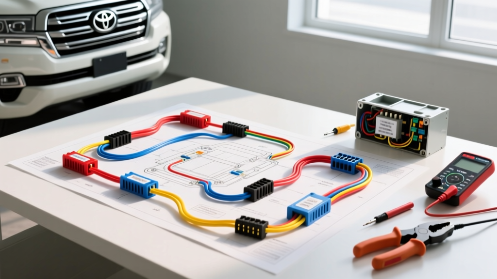
Introduction to Land Cruiser Electrical Architecture
Troubleshooting the electrical system of a Toyota Land Cruiser requires more than just a basic multimeter; it demands a methodical approach guided by the factory Toyota Land Cruiser wiring diagram. Whether you are working on the legendary 80 Series with the 4.5L 1FZ-FE inline-six, the 100 Series with the 4.7L 2UZ-FE V8, or the 200 Series platform, the electrical architecture relies on complex multiplex communications, precise sensor reference voltages, and robust but aging ground networks. Off-road vibrations, heat cycling, and exposure to the elements frequently degrade wire insulation and corrode connector cavities. This guide provides a step-by-step troubleshooting flow designed for automotive technicians and advanced DIYers to isolate faults efficiently without throwing unnecessary parts at the vehicle.
Pre-Diagnostic Safety & Tool Requirements
Before probing any circuits, ensure you have the correct diagnostic equipment to prevent back-probing damage to Yazaki and Sumitomo sealed terminals. Required tools include:
- Digital Multimeter (DMM): Must feature a minimum 10-Megohm input impedance to prevent drawing excessive current and damaging the Engine Control Module (ECM) logic boards.
- Power Probe or Fused Jumper Wires: For actuating relays and solenoids safely without exceeding circuit AWG ratings.
- T-Pin Back-Probes: Never pierce Toyota wire insulation with sharp probes; this invites copper oxidation and green rot, especially in harsh off-road environments.
- Terminal Release Tools: Specific to Toyota 0.64mm and 1.0mm female terminal cavities for safe connector disassembly.
Step 1: Decoding the Toyota Land Cruiser Wiring Diagram
To effectively use a Toyota Land Cruiser wiring diagram, you must understand Toyota's specific nomenclature and color-coding system. Toyota uses a Base/Tracer format for wire colors. For example, 'W/R' denotes a White wire with a Red tracer, while 'B/W' is Black with a White tracer. Standard color abbreviations include B (Black), W (White), R (Red), G (Green), Y (Yellow), BR (Brown), L (Blue), and GR (Gray).
Furthermore, Toyota diagrams map the physical routing of harnesses using specific connector designators. Engine bay connectors typically begin with 'E' (e.g., E4, E7), instrument panel connectors use 'I' or 'IH', and body/ground points use 'G' or 'B'. Splices are denoted by a circle with a cross inside, indicating a factory ultrasonic weld that should never be confused with a serviceable connector. When tracing a parasitic draw or an open circuit, always identify the exact cavity number within the connector block rather than relying solely on physical wire position, as harness wrapping can twist wires out of visual order.
Step 2: ECU Pinout Verification (1FZ-FE & 2UZ-FE)
The ECM is the brain of the Land Cruiser's powertrain. Verifying power, ground, and reference signals at the ECM connector is the most critical step in the troubleshooting flow. Below is a reference table for critical pins on the 80 Series 1FZ-FE ECM (Connector E4/E5), which is notoriously sensitive to voltage drops caused by corroded ground studs.
| Pin / Cavity | Function | Wire Color | AWG Size | Expected Voltage / State (KOEO) |
|---|---|---|---|---|
| E4 - Pin 1 | +B (Main EFI Power) | W/R | 14 AWG | Battery Voltage (12.2V - 12.6V) |
| E4 - Pin 2 | E1 (ECM Logic Ground) | BR | 16 AWG | Less than 0.05V drop to battery negative |
| E4 - Pin 9 | IGT (Igniter Signal) | B/Y | 20 AWG | Pulsing 0-5V during crank |
| E5 - Pin 14 | VSS (Vehicle Speed) | W/R | 20 AWG | Square wave, frequency scales with speed |
| E5 - Pin 21 | VC (Sensor Reference 5V) | V (Violet) | 20 AWG | Steady 4.8V - 5.1V |
Note: Always consult the Toyota Technical Information System (TIS) for the exact pinout matrix corresponding to your specific model year and production month, as mid-year harness revisions are common.
Step 3: Step-by-Step Troubleshooting Decision Trees
Use the following decision trees to isolate the most common Land Cruiser electrical faults. These flows assume you have already verified battery health and main fusible links.
Symptom A: Crank, No Start (No Fuel Pump Prime)
- Check EFI Main Relay: Locate the EFI relay in the engine bay fuse block. Verify 12V at the B/W (Black/White) feed wire. If missing, check the 15A EFI fuse and ALT-S fusible link.
- Verify Circuit Opening Relay (C/OPN): The C/OPN relay requires an RPM signal from the igniter to keep the fuel pump energized after the key leaves the 'START' position. Back-probe the L (Blue) wire at the C/OPN relay. If voltage drops to 0V immediately after releasing the key from 'START' to 'RUN', the ECM is not seeing an RPM signal (NE/G signal from the distributor or crank sensor).
- Inspect Fuel Pump Ground: The fuel pump grounds at the rear chassis near the fuel tank. Verify continuity to chassis ground. A corroded ground stud here will cause the pump to run slowly, leading to low fuel pressure (spec: 38-44 psi) and lean misfires under load.
Symptom B: Erratic Idle / MAF Sensor Codes (P0100/P0101)
- Verify 5V Reference: Back-probe the Violet (V) wire at the Mass Air Flow (MAF) sensor connector. If voltage reads below 4.8V, suspect a short to ground in the harness or a failing ECM 5V voltage regulator.
- Check Signal Return: Probe the Yellow (Y) signal wire. At idle, the 1FZ-FE should output approximately 1.8V to 2.2V. If the voltage is erratic, check for harness chafing where the engine harness passes through the firewall grommet near the brake booster.
- Inspect Intake Air Temperature (IAT) Circuit: The IAT is integrated into the MAF on later models. Verify the BR/Y (Brown/Yellow) ground wire has less than 1 ohm of resistance to the battery negative terminal.
Step 4: Grounding & Parasitic Draw Isolation
Land Cruisers utilize a distributed ground system. Poor grounds cause cascading failures, including erratic shifting, dim headlights, and false ABS codes. According to SAE J1171 Marine and Off-Road Electrical Standards, heavy-duty vehicles require rigorous ground termination protocols due to high-vibration environments.
Ground Stud Torque Specifications:
- Engine Block to Chassis Ground Strap (8 AWG): 15 Nm (11 ft-lb)
- ECM Logic Grounds at Kick Panel (16-18 AWG): 5 Nm (44 in-lb)
- Battery Negative to Frame (4 AWG): 24 Nm (18 ft-lb)
Parasitic Draw Testing Flow: A healthy Land Cruiser should draw less than 50mA (0.05A) after the CAN-bus and ECM modules go to sleep (typically 15-20 minutes after key-off). If your DMM reads higher:
- Disconnect the negative battery cable and connect the DMM in series (set to 10A max initially).
- Pull fuses one by one, waiting 30 seconds between each pull to allow modules to re-sleep if waking up.
- Common culprits include the aftermarket radio harness (constant 12V memory wire back-feeding), the A/C amplifier relay sticking closed, or a shorted diode in the 2UZ-FE alternator.
Step 5: Connector Repair and Harness Restoration
When the Toyota Land Cruiser wiring diagram leads you to a broken wire or corroded terminal, do not use twist-and-tape methods. Use the correct OEM-style crimping tools. For the engine bay, Toyota utilizes Sumitomi TS-series and Yazaki 0.64mm waterproof connectors. When replacing a terminal, you must use the correct silicone rubber weather pack seal. Crimp the wire barrel using a ratcheting micro-crimp tool, ensuring the wire insulation is crimped by the rear tabs and the bare copper by the front tabs. Apply a small amount of dielectric grease to the mating face of the connector before re-seating it to prevent moisture intrusion and galvanic corrosion.
For comprehensive mechanical and electrical teardown procedures, the Haynes Toyota Land Cruiser Repair Manual remains an excellent supplementary resource for identifying hidden harness routing clips and dash disassembly sequences required to access the body control modules and instrument cluster wiring.
Conclusion
Mastering the Toyota Land Cruiser wiring diagram is essential for maintaining the legendary reliability of these vehicles. By following a structured troubleshooting flow, verifying ECM pinouts with high-impedance tools, and adhering to strict ground termination standards, you can accurately diagnose and repair complex electrical faults, ensuring your Land Cruiser remains trail-ready for decades to come.