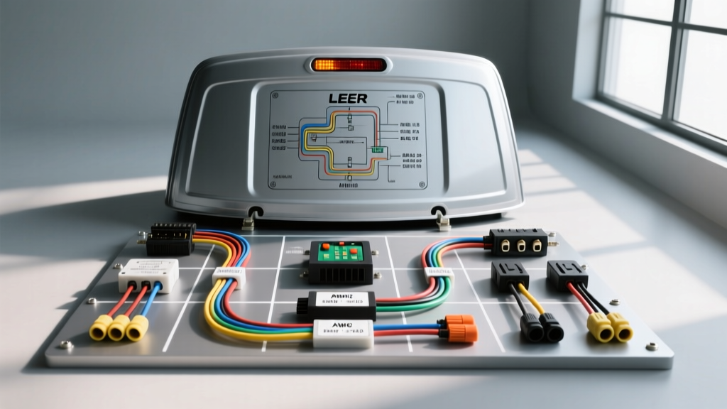
LEER Truck Cap Electrical Integration Overview
Integrating the electrical system of a LEER truck cap (such as the 100R, 100XQ, 122, or 180 series) requires a precise understanding of both the cap's internal harness and the host vehicle's tow package or tail light circuitry. When referencing a LEER truck cap wiring diagram, technicians and DIY enthusiasts must account for modern vehicle multiplexing, voltage drop over long wheelbases, and environmental sealing. Unlike standard trailer wiring, a truck cap requires permanent or semi-permanent routing for interior dome lights, cargo LED strips, and rear-facing exterior marker lights.
This technical specification reference outlines the standard SAE-compliant connector pinouts, wire gauge requirements, and Body Control Module (BCM) integration protocols necessary for a fault-free LEER cap installation.
Standard 7-Way RV Blade Connector Pinout (SAE J2862)
Most late-model trucks equipped with a factory tow package utilize a 7-way RV blade connector. This is the preferred integration point for a LEER cap, as it provides dedicated circuits for running lights, stop/turn signals, and a 12V auxiliary feed for interior lighting. Below is the standard SAE J2862 pinout configuration as viewed from the wiring side of the female connector on the truck cap harness.
| Pin Position | Wire Color | Function | Recommended AWG | LEER Cap Application |
|---|---|---|---|---|
| Center | White | Chassis Ground | 10 AWG | Main harness ground to cap frame |
| 1:00 | Brown | Tail / Marker Lights | 14 AWG | Exterior cap clearance/marker LEDs |
| 3:00 | Yellow | Left Stop / Turn | 14 AWG | Left rear exterior combination lamp |
| 5:00 | Blue | Electric Brakes | N/A | Not used in truck cap applications |
| 7:00 | Green | Right Stop / Turn | 14 AWG | Right rear exterior combination lamp |
| 9:00 | Black | 12V Auxiliary Power | 10 AWG | Interior dome lights, cargo LEDs |
| 11:00 | Purple | Reverse Lights | 14 AWG | Rear flood/work lights (if equipped) |
4-Way Flat Connector Alternative
For base-model trucks lacking a factory 7-way tow package, a 4-way flat connector is typically spliced into the truck's tail light harness using a T-connector (such as those manufactured by Curt Manufacturing). The 4-way flat provides only the essentials:
- White (Ground): Must be securely ring-terminated to a bare metal point on the truck bed or frame. Do not rely on sheet metal screws into painted bed sheets.
- Brown (Tail): Spliced into the OEM running light circuit.
- Yellow (Left): Spliced into the OEM left stop/turn circuit.
- Green (Right): Spliced into the OEM right stop/turn circuit.
Note: When using a 4-way flat, the LEER cap's interior dome light must be wired separately, typically by running a dedicated 12 AWG wire from the vehicle's battery (with a 15A inline ATO fuse) or tapping into an upfitter switch circuit.
Multiplexed (PWM) vs. Analog Tail Light Systems
A critical consideration in modern LEER truck cap wiring diagrams is the shift from analog 12V switching to Pulse Width Modulation (PWM) and CANbus-monitored circuits. Vehicles such as the 2011+ Ford F-150, 2019+ RAM 1500, and 2014+ Chevrolet Silverado utilize the BCM to monitor tail light current draw.
The LED Hyperflash and BCM Fault Issue
LEER caps frequently feature low-draw LED exterior marker lights. Because LEDs draw significantly less current than incandescent bulbs, the truck's BCM may interpret the low amperage as a "bulb out" condition. This results in:
- Hyperflashing of the turn signals.
- Intermittent cutting out of the tail lights while driving.
- BCM diagnostic trouble codes (DTCs) and dashboard warning messages.
Resolution: Load Resistors and CANbus Decoders
To resolve PWM detection faults, you must install 6-ohm, 50-watt load resistors in parallel with the LED marker lights on the brown (tail) and yellow/green (turn) circuits. Alternatively, install an inline CANbus decoder module specifically rated for LED trailer/cap lighting to simulate the correct amperage draw without generating excess heat.
Dome Light and Auxiliary Power Routing
The interior LED dome light in a LEER cap is traditionally wired to the 7-way connector's Black (12V Aux) wire. However, the behavior of this circuit varies by OEM:
- Ford/GM: The 12V Aux pin is often hot only when the ignition is in the "Run" or "Accessory" position, or it may be controlled by a specific BCM relay that times out after 10 minutes of the doors being locked.
- RAM/Stellantis: May require a specific configuration in the Uconnect infotainment system to enable continuous 12V power to the tow package aux pin.
OEM Upfitter Switch Integration (Pro-Tip)
For users requiring on-demand control of the LEER cap dome light or exterior bed-rail light bars regardless of ignition state, routing the cap's 12V auxiliary wire to the truck's Upfitter Switch Bank is the superior method.
- Locate the OEM upfitter relay block (typically under the hood near the firewall or in the engine bay fuse box).
- Identify the desired upfitter circuit (e.g., AUX 1, rated for 25A).
- Run a 12 AWG GXL wire from the upfitter terminal, through the firewall grommet, down the frame rail, and up into the truck bed.
- Splice this dedicated 12V feed directly to the LEER cap's interior switch pod power feed, bypassing the 7-way Black wire entirely.
Wire Selection, AWG Sizing, and Environmental Sealing
Truck cap wiring is subjected to extreme thermal cycling, road salt, and moisture. Standard PVC-jacketed wire (THHN) is unacceptable for underbody routing. According to SAE J1128 standards, automotive primary wire must be used.
| Wire Type | Insulation Material | Temp Rating | Application in LEER Cap Install |
|---|---|---|---|
| GXL | Cross-Linked Polyethylene | 125°C | General cap lighting, marker lights, 7-way pigtails |
| SXL | Cross-Linked Polyethylene | 125°C (Thicker wall) | Underbody frame routing, high-vibration areas |
| TXL | Cross-Linked Polyethylene | 125°C (Thin wall) | Interior cap routing, switch pod harnesses |
Splice Sealing Methodology
Capillary action can draw moisture through the copper strands of a wire if a splice is left exposed, eventually corroding the LED driver inside the LEER cap. All underbody splices must be sealed using dual-wall adhesive-lined heat shrink. The inner wall melts and forms a watertight seal, while the outer wall provides mechanical abrasion resistance. Apply a dab of dielectric grease to all 7-way and 4-way connector pins prior to mating to prevent galvanic corrosion between the brass pins and the vehicle's receptacle.
Diagnostic Troubleshooting Matrix
When diagnosing faults in a LEER truck cap wiring diagram, use a digital multimeter (DMM) to perform voltage drop tests rather than relying solely on test lights, which do not reveal high-resistance ground faults.
- Symptom: Cap dome light is dim; truck dash lights flicker when cap door is opened.
Cause: High resistance on the White ground wire or undersized ground AWG.
Fix: Upgrade ground to 10 AWG, clean frame contact point to bare metal, and apply anti-corrosion compound. - Symptom: Left turn signal hyperflashes on dash, but cap left LED blinks normally.
Cause: BCM detects low amperage draw from LED cap markers.
Fix: Install 6-ohm 50W load resistor in parallel on the Yellow wire circuit. - Symptom: 12V Aux (Black wire) has 0V at the cap plug, but fuses are intact.
Cause: OEM tow package relays not installed or BCM logic requires ignition "ON".
Fix: Check under-hood fuse box for missing "Tow Package" or "Trailer Aux" relays (common in Ford Super Duty and F-150 platforms).
Authoritative References
For further engineering specifications regarding connector layouts and wire insulation standards, refer to the SAE J2862 7-Way Connector Standard and the LEER Group Official Owner Resources for model-specific harness routing diagrams.