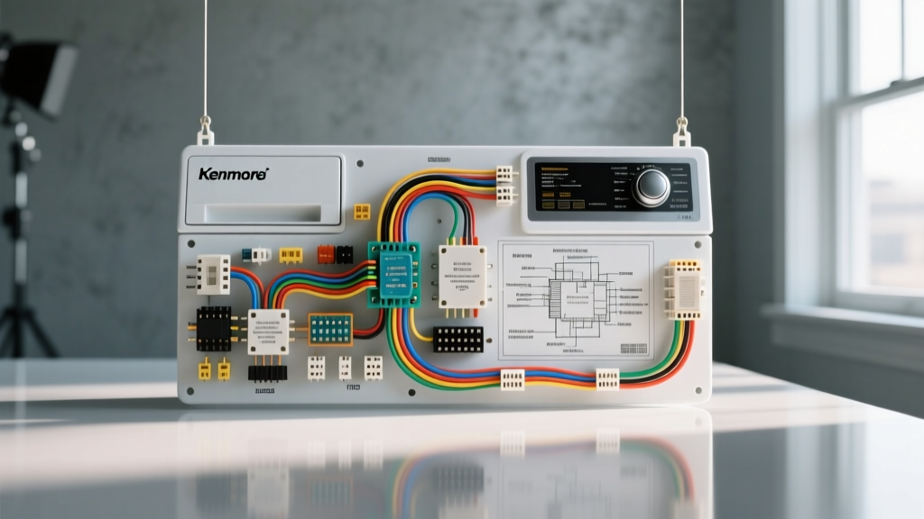
Why Automotive Techs Start with Appliance Schematics
Before you can diagnose a complex CAN-bus communication fault or trace a parasitic draw in a modern vehicle, you must master the foundational logic of electrical circuits. At AutoflowWire, we frequently train new technicians using a seemingly unrelated resource: the wiring diagram for Kenmore dryer model 110. Why? Because this specific appliance schematic is a masterclass in series-parallel logic, thermal protection, and motor-start switching. The principles governing a 240V AC split-phase appliance directly translate to the 12V DC systems found in automotive HVAC, starting, and PCM-controlled circuits.
This beginner-friendly guide deconstructs the Kenmore 110 schematic and maps its core electrical concepts directly to automotive equivalents, giving you the schematic literacy required for advanced vehicle diagnostics.
Deconstructing the Wiring Diagram for Kenmore Dryer Model 110
The Kenmore Series 110 dryer (often manufactured by Whirlpool) operates on a NEMA 14-30 receptacle, delivering split-phase 240V AC alongside a 120V neutral. Understanding how this power is distributed is your first lesson in load management.
1. The Power Distribution Matrix
- L1 (Black Wire): 120V AC. Powers the timer motor, control board, and one side of the heating element.
- L2 (Red Wire): 120V AC. Powers the main drive motor and the opposite side of the heating element.
- Neutral (White Wire): The return path for 120V components. In automotive terms, this is the functional equivalent of the vehicle chassis ground.
- Ground (Green/Bare): Safety earth ground. Never carries current unless a fault occurs.
Automotive Translation: In a vehicle, the 12V battery positive (B+) is analogous to L1/L2, while the vehicle's steel chassis serves as the Neutral/Ground return. When reading an automotive schematic, any component that doesn't have a dedicated ground wire is using the chassis as its 'White Wire' return path.
2. The Centrifugal Motor Switch
The Kenmore 110 drive motor utilizes a start winding and a run winding. When power is applied, a centrifugal switch engages the start winding to provide initial torque. Once the motor reaches ~75% RPM, centrifugal force throws the switch open, dropping the start winding and leaving the motor on the run winding. Furthermore, this same switch acts as a safety interlock: if the motor stops, the switch closes, cutting power to the heating element to prevent a fire.
Automotive Translation: This exact logic applies to an automotive starter solenoid. The solenoid uses a high-current 'pull-in' winding to engage the Bendix gear with the flywheel, and a lower-current 'hold-in' winding to keep it engaged. Additionally, modern fuel pump relays use an oil-pressure switch interlock—a direct parallel to the dryer's motor-heater safety interlock.
Translating 240V AC Appliance Logic to 12V DC Automotive Systems
Let's compare the high-amperage heating circuits in the Kenmore 110 to a common high-amperage automotive circuit: the rear window defroster grid.
| Specification | Kenmore 110 Heating Element | Automotive Rear Defroster Grid |
|---|---|---|
| Voltage Source | 240V AC (L1 to L2) | 12V - 14.4V DC (B+ to Chassis) |
| Amperage Draw | ~22.5 Amps (5400 Watts) | ~30 to 40 Amps |
| Wire Gauge (AWG) | 10 AWG Copper | 10 AWG Copper (Feed wire) |
| Primary Protection | 30A Time-Delay Breaker | 30A or 40A Maxi-Fuse |
| Secondary Protection | Thermal Fuse (Cutoff at 250°F) | PCM/BCM Thermistor PWM Control |
Notice that despite the massive difference in voltage, the 10 AWG wire gauge requirement remains identical because the amperage (the actual work and heat generated) is nearly the same. According to the NFPA 70 National Electrical Code, 10 AWG copper is rated for 30 amps, a rule that applies whether you are wiring a household appliance or routing a harness through a vehicle's A-pillar.
Schematic Symbol Translation: SAE vs. Appliance Standards
One of the biggest hurdles for beginners is learning to read different schematic dialects. Appliance diagrams use functional, physical layouts, while automotive diagrams follow strict SAE J1234 symbol standards.
Switches and Contacts
- In the Kenmore Diagram: The timer switch is drawn as a literal rotary dial with multiple physical contact points (e.g., 'Timer to Ground', 'Timer to Heater'). It looks like a physical map of the component.
- In Automotive Schematics: A multi-position switch (like a turn signal stalk) is drawn using standardized SAE logic gates and dashed lines indicating mechanical linkage. You must learn to follow the dashed lines to understand which pins close simultaneously.
Ground Symbols
- Appliance: Ground is often drawn as a literal earth rod symbol or a chassis line, explicitly wired back to the neutral bus.
- Automotive: Ground symbols (G101, G204) represent specific physical bolt locations on the vehicle chassis. A bad G204 ground will cause a 12V sensor to backfeed through the CAN-bus, a concept that doesn't exist in a simple 240V appliance loop.
Real-World Failure Modes & Multimeter Diagnostics
Applying the ASE Electrical/Electronic Systems (A6) testing methodology, let's look at how a failure in the Kenmore 110 translates to automotive troubleshooting.
The Thermal Fuse vs. The Fusible Link
The Kenmore 110 features a thermal fuse on the blower housing. If the exhaust vent is clogged, heat builds up, and the one-time-use thermal fuse melts, breaking the circuit. The dryer will run, but produce no heat.
Automotive Equivalent: An automotive fusible link (often found in the main under-hood fuse box) protects high-current circuits like the alternator B+ feed. If an alternator diode rectifier fails and shorts, the fusible link melts to prevent a harness fire.
Diagnostic Step: Set your multimeter to Continuity (Ohms). Disconnect power. Probe both sides of the thermal fuse or fusible link. An 'OL' (Open Loop) reading confirms a blown protective device. Never simply bypass the fuse; you must find the root cause (clogged vent or shorted diode).
Voltage Drop Testing the Neutral vs. Chassis Ground
In the Kenmore 110, if the Neutral (White) wire becomes corroded at the terminal block, the 120V timer motor won't run, even though the 240V heater might still partially energize through a backfeed. This is a 'lost return path' issue.
Automotive Equivalent: A corroded ECU ground pin. If the PCM's main ground has 2 volts of resistance, a 5V reference sensor will read 7V, causing the engine to run rich and throw a phantom O2 sensor code.
Diagnostic Step: Perform a Voltage Drop Test. Keep the circuit loaded (turn the dryer timer on, or crank the engine). Place your red multimeter probe on the battery positive/switched side, and the black probe on the ground side of the load. A reading above 0.1V on a 12V automotive ground circuit indicates high resistance requiring harness repair.
Safety Protocols: Lockout/Tagout vs. Battery Disconnect
Working on the wiring diagram for Kenmore dryer model 110 involves lethal 240V AC potentials. The mandatory safety protocol is Lockout/Tagout (LOTO) at the main breaker panel. In automotive 12V DC systems, while the voltage won't electrocute you, a shorted 10 AWG wire can instantly weld a wrench to the chassis and start a lithium or lead-acid battery fire. Always disconnect the negative battery terminal and isolate it with a non-conductive boot before probing any SRS (airbag) or PCM harness. Treat every schematic with the same respect, whether it's powering a heating element or an electronic throttle body.