Why Upgrade to a 6-Prong Ignition Switch?
When restoring classic John Deere garden tractors (such as the 318, 420, or LX series) or executing an engine repower project, the factory ignition system often becomes a bottleneck. Many older models utilized 4-prong or 5-prong switches that lack a dedicated magneto kill circuit or accessory position. Upgrading to an OEM-style 6-prong ignition switch (commonly replacing part numbers like AM105060 or AM107373) provides superior circuit isolation, integrates modern safety interlocks, and supports the voltage regulator requirements of repowered engines like the Kohler Command or Kawasaki FD series.
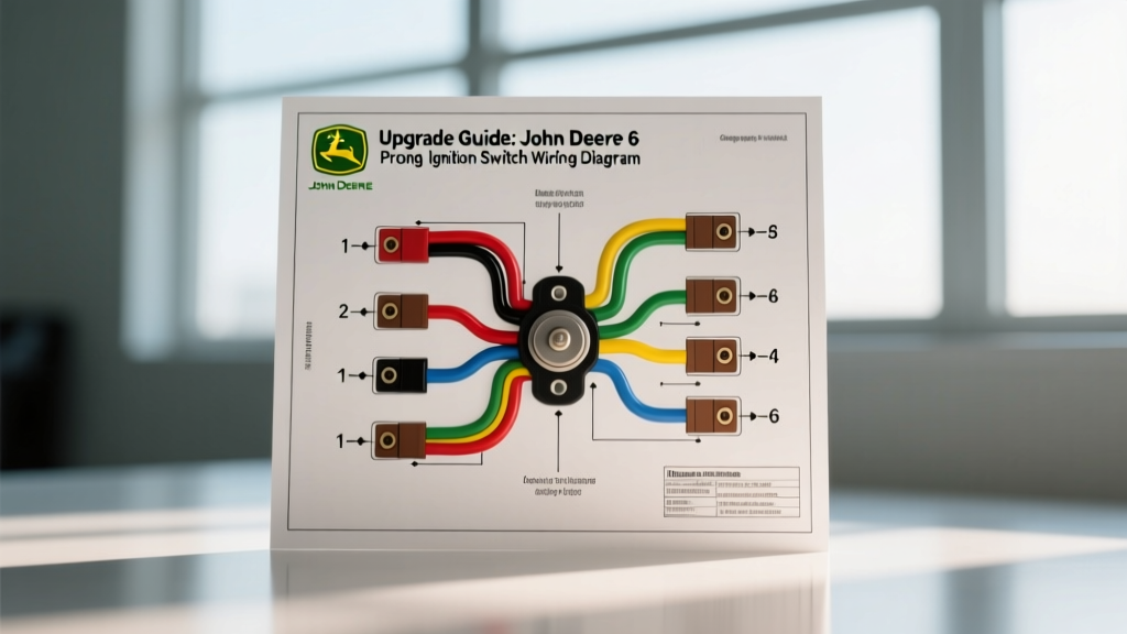
This comprehensive john deere 6 prong ignition switch wiring diagram and modification guide will walk you through the exact terminal pinouts, wire gauge requirements, and routing strategies needed to safely upgrade your tractor's electrical harness without frying the stator or ignition module.
Terminal Pinout and Wire Routing Specifications
The standard John Deere 6-prong switch utilizes a specific terminal layout designed to separate the high-amperage starter circuit from the sensitive solid-state voltage regulator and magneto kill circuits. Below is the definitive reference chart for your modification project.
| Terminal ID | Label | Function / Destination | Recommended AWG | Standard Wire Color |
|---|---|---|---|---|
| B | Battery | Main 12V+ Input (from Starter Solenoid / Battery via 20A Fuse) | 12 AWG | Red |
| S | Start | 12V+ Output to Starter Solenoid Trigger Spade | 14 AWG | Red/White Tracer |
| I | Ignition | 12V+ Output to Voltage Regulator (B+ Terminal) and PTO Relay Coil | 16 AWG | White or Yellow |
| G | Ground | Chassis Ground / Safety Interlock Module Ground Path | 16 AWG | Black |
| M | Magneto | Ground Output to Engine Ignition Coil / Module Kill Wire | 16 AWG | Black/Yellow Tracer |
| L / A | Lights / Acc | 12V+ Output to Headlight Switch or Auxiliary PTO Circuit | 14 AWG | Brown |
Step-by-Step Upgrade & Modification Procedure
Step 1: Harness Depinning and Voltage Drop Testing
Before cutting or splicing, disconnect the battery negative terminal. Remove the old switch and inspect the OEM harness. Older John Deere tractors are notorious for corroded spade terminals causing severe voltage drops. Using a multimeter, perform a voltage drop test on the existing 'B' (Battery) wire. According to SAE J1128 standards for automotive primary wire, any voltage drop exceeding 0.2V under load on the main feed indicates high resistance. If your original harness utilizes undersized 14 AWG wire for the main battery feed, upgrade the 'B' circuit to 12 AWG GXL or TXL cross-linked polyethylene wire to handle the inrush current of the starter solenoid without melting the switch casing.
Step 2: Integrating the Magneto Kill (M Terminal) for Repowers
The most critical aspect of this upgrade is the 'M' (Magneto) terminal. If you are swapping out a Briggs & Stratton engine for a Kawasaki or Kohler, the new engine's ignition module requires a dedicated ground path to kill the spark. Warning: Never confuse the 'I' (Ignition) and 'M' (Magneto) terminals. The 'I' terminal outputs 12V+ to the alternator's voltage regulator. The 'M' terminal provides a ground path to short out the magneto coil. If you accidentally wire the 12V+ 'I' feed into the engine's magneto kill wire, you will instantly destroy the engine's ignition module upon turning the key. Route a 16 AWG Black/Yellow wire from the 'M' terminal directly to the engine's kill spade, ensuring it is isolated from the 12V+ harness.
Step 3: Upgrading Connectors and Weatherproofing
The factory John Deere switches often fail due to moisture ingress causing internal corrosion. When performing this modification, discard standard vinyl-insulated ring and spade terminals. Instead, use adhesive-lined heat shrink terminals or, for a true professional-grade harness rebuild, upgrade to TE Connectivity AMP sealed connectors. Apply dielectric grease (such as Nyogel 760G) to the switch spades before sliding the new 6-prong boot into place to prevent galvanic corrosion between the copper wire and brass terminals.
Integrating Safety Interlocks (PTO and Seat Switches)
Modernizing a classic John Deere tractor requires integrating safety interlocks. The 6-prong switch's 'G' (Ground) terminal is frequently used in conjunction with a PTO safety relay.
- The Logic: When the key is turned to the 'OFF' position, the internal wiper connects the 'M' (Magneto) terminal to the 'G' (Ground) terminal, killing the engine.
- The Modification: To add a seat safety switch, wire the seat switch in series with the 'G' terminal's ground path. If the operator leaves the seat with the PTO engaged, the safety relay interrupts the ground path to the ignition module, safely killing the engine via the 'M' circuit.
Troubleshooting Common Modification Failures
Even with a perfect wiring diagram, field modifications can present unique electrical gremlins. Use this decision tree to diagnose post-upgrade issues:
Symptom: Engine Cranks but Will Not Shut Off
- Cause 1: The 'M' (Magneto) terminal is not making contact with the 'G' (Ground) terminal internally when the key is in the OFF position. Fix: Test switch continuity with a multimeter. Replace if defective.
- Cause 2: Broken ground path between the switch casing/G-terminal and the tractor chassis. Fix: Run a dedicated 16 AWG ground wire from the 'G' terminal directly to the engine block or battery negative.
- Cause 3: Diode failure in the voltage regulator allowing back-feed voltage to keep the ignition module energized. Fix: Install a blocking diode on the 'I' terminal wire.
Symptom: Starter Solenoid Clicks but Engine Won't Turn Over
- Cause 1: Voltage drop across the 'B' to 'S' internal switch contacts. High-amperage solenoids require a strong 12V+ trigger signal. Fix: Install a 30A automotive relay triggered by the 'S' terminal to carry the main solenoid load, bypassing the ignition switch's internal wiper limits.
- Cause 2: Undersized wire on the 'S' terminal. Fix: Upgrade the 'S' terminal wire to 14 AWG or 12 AWG.
Symptom: Headlights Flicker or Dim at Low RPM
- Cause: The 'L/A' (Lights/Accessory) terminal is drawing power directly from the 'B' feed, which may be shared with the starter solenoid's high-resistance path. Fix: Wire the 'L/A' terminal to a dedicated fused relay block powered directly from the battery, using the ignition switch only as a low-amperage trigger signal.
Final Verification and Torque Specs
Once all 6 prongs are terminated and routed away from the steering shaft and exhaust headers, perform a final continuity check. Verify that the 'B' terminal reads 12.6V+ at all times. Ensure the 'M' terminal shows continuity to ground only when the key is in the OFF position. When tightening the mounting nut on the switch bezel, do not exceed 15 in-lbs of torque, as overtightening will crack the Bakelite or plastic housing, leading to premature moisture intrusion and internal arcing. By following this schematic and utilizing proper automotive-grade wiring techniques, your John Deere tractor will feature a reliable, modern ignition system capable of handling decades of heavy-duty use.