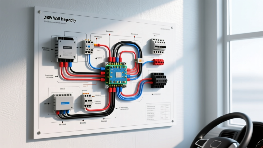
Introduction to Mobile 240V Heating Systems
While residential HVAC systems are common, integrating a high-voltage electric heater into a mobile platform introduces severe engineering and diagnostic challenges. When referencing the 240v wall heater wiring diagram for your heavy-duty sleeper cab, expedition RV, or marine vessel, you are no longer dealing with a static utility grid. Instead, the heater is likely powered by a split-phase 240V inverter system drawing from a massive 48V DC battery bank, or routed through an Automatic Transfer Switch (ATS) connected to a shore power pedestal. Vibration, thermal cycling, and complex Neutral-Ground bonding topologies create distinct failure modes that standard residential electricians often misdiagnose. This guide provides a step-by-step troubleshooting flow tailored specifically for automotive and heavy-duty vehicular environments.
Pre-Diagnostic Safety & Lockout Protocols
Before touching a single terminal, you must respect the lethal nature of mobile 240V AC systems. Unlike a house where flipping a breaker guarantees isolation, a vehicular inverter can backfeed AC voltage from the DC battery bank if the internal transfer relays fail.
- Disconnect Shore Power: Unplug the L6-20R twist-lock shore cable.
- Isolate the DC Source: Open the main battery disconnect switch or remove the 4/0 AWG ANL fuse on the positive DC feed to the inverter.
- Verify Zero Energy: Use a True-RMS multimeter (CAT III rated) to test L1 to L2, L1 to Ground, and L2 to Ground at the heater disconnect. You must read 0.0V before proceeding.
Step-by-Step Troubleshooting Flow
Step 1: Isolate the Power Source (ATS & Inverter)
The most common reason a 240V cab heater fails to engage is an Automatic Transfer Switch (ATS) fault. The ATS decides whether to pass current from the shore inlet or the inverter. If the ATS relay contacts are pitted from arcing during high-inductive load switching (like an AC compressor starting), the 240V leg may drop.
- Test: With shore power connected, measure voltage at the ATS output. You should read 240V across L1 (Black) and L2 (Red).
- Fault Condition: If you read 120V across L1-Neutral and 0V across L2-Neutral, the ATS has failed to close the L2 pole, or the inverter's split-phase secondary winding has dropped out.
Step 2: Verify Split-Phase Line Voltage
Mobile 240V inverters (such as the Victron Quattro or OutBack Radian) generate split-phase power by using a center-tapped transformer or dual synchronized inverters. The L1 and L2 legs must be exactly 180 degrees out of phase.
- Target Reading: L1 to L2 = 240V. L1 to Neutral = 120V. L2 to Neutral = 120V.
- Inverter Sync Failure: If L1-L2 reads 120V instead of 240V, the inverter's internal sync relay is stuck, or the firmware has lost phase synchronization. The heater will only receive 1/4th of its rated wattage (since Power = Voltage² / Resistance), resulting in barely warm air.
Step 3: Thermostat and Control Circuit Continuity
Vehicular 240V wall heaters often use line-voltage thermostats to handle the combined resistive load of the heating element and the inductive load of the blower motor. Vibration can cause the internal bimetallic strips or mercury switches (in older models) to fail.
- Bypass Test: Disconnect the two line-voltage wires at the thermostat. Connect them together using a WAGO lever nut. If the heater blower and element engage, the thermostat is faulty or has lost its thermal coupling to the cab wall.
- Micro-Voltage Drop: Measure voltage across the closed thermostat contacts under load. A reading above 0.5V indicates severe internal pitting requiring immediate replacement.
Step 4: Heating Element Resistance & Ground Faults
Mobile environments subject heating elements to constant micro-vibrations, which can cause the internal Nichrome wire to fracture or sag and touch the grounded metal casing, tripping the GFCI breaker.
- Resistance Calculation: A standard 2000W heater at 240V draws 8.3 Amps. Using Ohm's Law (R = V² / P), the target resistance is 28.8 Ohms. Set your multimeter to Ohms and measure across the element terminals. An 'OL' (Open Line) reading means the element is fractured.
- Insulation Breakdown: Use a Megohmmeter (Megger) set to 500V DC. Test from the element terminal to the heater chassis ground. Any reading below 2 Megohms indicates insulation breakdown due to moisture ingress or vibration fatigue, requiring element replacement.
Vehicular 240V Heater Wiring Specifications
Standard residential electrical codes (NEC) do not fully account for the vibration and thermal derating inherent in truck cabs and RVs. The Recreational Vehicle Industry Association (RVIA) and SAE standards mandate stricter wire gauge and torque specifications for mobile AC branch circuits.
| Heater Wattage | Amp Draw (240V) | Minimum Wire Gauge (Mobile) | Breaker Size | Terminal Torque Spec |
|---|---|---|---|---|
| 1500W | 6.25A | 12 AWG (Stranded) | 15A (GFCI) | 20 in-lbs |
| 2000W | 8.33A | 12 AWG (Stranded) | 15A (GFCI) | 20 in-lbs |
| 3000W | 12.50A | 10 AWG (Stranded) | 20A (GFCI) | 30 in-lbs |
| 4000W | 16.66A | 8 AWG (Stranded) | 25A (GFCI) | 40 in-lbs |
Note: Always use fine-stranded, tinned copper wire (e.g., THHN/MTW) in mobile applications. Solid core wire will work-harden and snap under chassis vibration.
The Neutral-Ground Bonding Dilemma
One of the most misunderstood aspects of troubleshooting a 240v wall heater wiring diagram in a vehicle is the Neutral-Ground (N-G) bond. In a stationary home, the N-G bond occurs at the main service panel. In a mobile 240V system, the bond must switch depending on the power source.
When connected to shore power, the N-G bond is established at the utility pedestal. The inverter must not bond Neutral to Ground, or current will return via the chassis, causing severe galvanic corrosion and tripping pedestal GFCI breakers. When running off the inverter, the inverter's internal bonding relay must close to create the N-G bond, allowing the heater's GFCI breaker to detect ground faults properly. If your 240V heater GFCI trips instantly when switching to inverter power, but works fine on shore power, the inverter's N-G bonding relay is likely stuck open or closed, confusing the fault-sensing toroid in the breaker.
Common Failure Modes in High-Vibration Environments
- Terminal Back-Out: Push-in wire connectors are strictly prohibited in mobile 240V AC circuits. Vibration will cause the wire to slowly back out, creating a high-resistance arc fault. Always use screw-terminal blocks torqued to manufacturer specifications.
- Inverter Overload: A 2000W resistive heater draws 8.3A continuously. However, if the heater includes a blower motor, the inductive startup surge can spike to 25A for 500 milliseconds. If the inverter's peak surge rating is exceeded, it will hard-shutdown, dropping all AC power in the cab.
- Chassis Ground Loops: If the heater's green grounding wire is bonded to a painted or corroded chassis point rather than the dedicated AC grounding busbar, a ground fault will energize the entire truck sleeper frame, posing a fatal shock hazard to anyone touching the cab and the ground simultaneously.
Authoritative References
For further reading on mobile electrical safety and high-voltage integration, consult the following standards:
- SAE J1113: Electromagnetic Compatibility Standards - Guidelines for preventing inverter EMI from interfering with vehicular ECU and sensor networks.
- NFPA 70 (NEC) Article 551 - National Electrical Code specifications for Recreational Vehicles, shore power bonding, and transfer switch isolation.
- FMCSA 49 CFR § 393.89 - Federal Motor Carrier Safety Administration regulations regarding heavy-duty truck electrical system protection and routing.