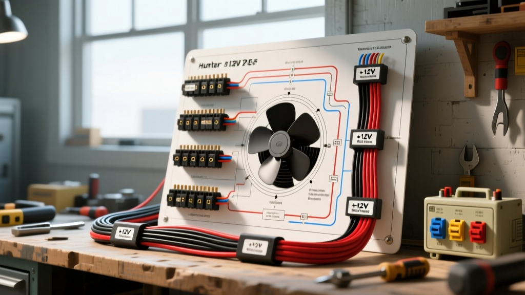
The Camper Van Ventilation Challenge: AC Logic vs. DC Reality
When DIY campervan builders and overland rig fabricators design interior ventilation systems, they often seek the quiet, multi-speed reliability of residential ceiling fans. Many DIYers begin their research by looking up a standard hunter fan wiring diagram fan switch, hoping to replicate the elegant 3-speed or 4-speed control logic in their 12V DC Sprinter, Transit, or Promaster builds. However, adapting residential AC switching components to a 12V DC automotive environment is a fundamental electrical mistake that frequently leads to melted switch housings, arcing, and catastrophic fire hazards.
As an automotive electrical specialist, I frequently see RV owners attempt to wire a 12V DC marine or automotive ventilation fan using a residential Hunter wall switch. This guide breaks down the physics of why the OEM Hunter fan wiring diagram fan switch fails in DC applications, and provides a comprehensive, beginner-friendly schematic for safely replicating multi-speed fan control using automotive-grade 12V relays and PWM (Pulse Width Modulation) logic.
Deconstructing the OEM Hunter Fan Wiring Diagram Fan Switch
To understand why residential switches fail in vehicles, we must first examine how the OEM Hunter fan switch actually works on a 120V AC grid. The standard Hunter 3-speed or 4-speed switch does not use resistors to drop voltage; instead, it utilizes a bank of AC capacitors (typically rated in microfarads, such as 2.5µF, 5µF, and 7.5µF) wired in parallel and series configurations.
Standard Residential Wire Colors and Pinouts
- Black (Line In): 120V AC Hot feed from the breaker panel.
- White (Neutral): Completes the AC circuit back to the panel (often bypassed at the switch and spliced directly in the canopy).
- Red, Blue, Yellow (Load Out): These wires route through the internal capacitor bank to feed the auxiliary start winding of the AC induction motor, creating phase shifts that dictate motor speed (Low, Medium, High).
Because capacitors inherently block Direct Current (DC), wiring this exact Hunter switch layout to a 12V DC battery bank and a DC brushless fan will result in an open circuit. The fan will not spin, and the switch will serve no functional purpose. Furthermore, attempting to use the switch to simply break the main 12V positive feed ignores the severe dangers of DC arcing.
The Danger of DC Arcing in Residential Switches
The most critical difference between your vehicle's 12V DC system and your home's 120V AC system is how electrical arcs behave when a mechanical switch is opened under load. According to the NFPA 70 (National Electrical Code) Article 551, which governs RV and camper low-voltage systems, DC switches require vastly different internal contact geometries and snap-action mechanisms than AC switches.
Why AC Switches Melt on DC Loads
Alternating Current (AC) crosses the zero-voltage threshold 120 times per second (on a 60Hz grid). Every time the sine wave crosses zero, any electrical arc that forms between the opening switch contacts is naturally extinguished. Direct Current (DC), however, is a continuous, unidirectional flow of electrons. When you open a residential Hunter switch on a 12V DC inductive load (like a fan motor), the magnetic field collapsing inside the motor induces a high-voltage flyback spike. This sustains a continuous plasma arc across the switch contacts.
Because residential Hunter switches lack the internal blow-out magnets or rapid-snap mechanisms required to stretch and break a DC arc, the arc will burn continuously, generating extreme heat. This will melt the plastic switch housing, weld the internal contacts together (making the fan impossible to turn off), and potentially ignite the surrounding wood paneling in your camper van.
The Automotive Solution: Replicating Multi-Speed Logic Safely
To achieve the multi-speed control promised by a Hunter fan wiring diagram fan switch in a 12V vehicle environment, you must remove the high-amperage load from the physical dashboard switch. We do this by using the dashboard switch solely as a low-amperage signal trigger for automotive-grade Bosch-style relays or a solid-state PWM motor controller.
Required Materials and Wire Gauges
Adhering to SAE J1128 standards for low-tension primary automotive cable, we must select the correct wire gauge based on the physical distance and amperage draw of the 12V DC fan.
- Primary Power Feed: 12 AWG stranded copper wire (Red) for the main battery feed to the relay bank.
- Switch Trigger Wires: 18 AWG stranded copper wire (Blue/Yellow/Green) for the dashboard switch signals.
- Relays: Three 30A SPST (Single Pole Single Throw) Bosch-style automotive relays with integrated flyback diodes.
- Protection: 30A MAXI fuse for the main power line, and a 5A ATC fuse for the switch trigger circuit.
- Terminals: Deutsch DT series or fully insulated female spade connectors with heat-shrink crimps.
Step-by-Step 12V Relay Wiring Schematic
This setup replicates a 3-speed fan switch logic safely. Instead of capacitors, we will use a multi-tap DC motor or inline resistors on the relay outputs to drop voltage for 'Low' and 'Medium' speeds, while 'High' receives full 12V battery voltage.
Step 1: Wiring the Main Power Circuit (Relay Pin 30)
Run a 12 AWG Red wire from your vehicle's auxiliary 12V busbar (or directly from the house battery bank positive terminal). Install a 30A ATC fuse holder within 6 inches of the power source. Route this 12 AWG wire to the dashboard area and splice it to feed Pin 30 on all three of your automotive relays. Pin 30 is the common high-amperage input.
Step 2: Wiring the Switch Triggers (Relay Pin 86)
Mount a heavy-duty, automotive-rated 3-position rotary switch on your dashboard. Connect an 18 AWG wire from a switched 5A fuse source to the common input terminal of the rotary switch. From the three output terminals of the rotary switch, run three separate 18 AWG wires (e.g., Yellow for Low, Green for Medium, Blue for High) to Pin 86 on each respective relay. Pin 86 is the low-amperage trigger input.
Step 3: Completing the Relay Coil Circuit (Relay Pin 85)
Daisy-chain an 18 AWG Black wire across Pin 85 on all three relays, and terminate this wire to a clean, bare-metal chassis ground. Pin 85 completes the electromagnetic coil circuit, pulling the internal relay contact closed.
Step 4: Wiring the Fan Load (Relay Pin 87)
Run a 12 AWG wire from Pin 87 on the 'High' relay directly to the positive terminal of your 12V DC fan motor. For the 'Medium' and 'Low' relays, route the 12 AWG wire from Pin 87 through high-wattage ceramic power resistors (or a PWM step-down module) before connecting to the fan's positive input. When you turn the dash switch to 'Low', only the Low relay engages, sending 12V through the resistor, dropping the voltage at the fan to roughly 7V for slow, quiet operation.
Technical Specifications: OEM Hunter vs. Automotive Relay Setup
| Feature | OEM Hunter Residential Switch | Automotive 12V Relay Bank |
|---|---|---|
| System Voltage | 120V AC (60Hz) | 12V - 14.4V DC |
| Speed Control Method | AC Capacitor Phase Shifting | DC Resistors / PWM Step-Down |
| Switch Amperage Rating | ~2A to 5A (AC Only) | Signal: <1A DC / Load: 30A DC |
| Arc Suppression | None (Relies on AC Zero-Crossing) | Flyback Diodes across Relay Coils |
| Wire Gauge Required | 14 AWG Solid Copper (NEC) | 12 AWG Stranded (SAE J1128) |
Troubleshooting Common 12V Fan Switch Failures
Even with a properly engineered automotive relay setup, 12V DC camper van systems are subject to vibration, voltage drop, and alternator noise. Use this diagnostic tree if your multi-speed fan setup fails to operate correctly.
Symptom: Fan runs on 'High' but will not drop to 'Low' or 'Medium'
- Cause: Backfeeding through the motor's internal circuitry. If you wire multiple relay outputs directly together without isolation diodes, the 12V from the 'High' relay will backfeed through the fan motor and into the 'Low' resistor circuit, energizing all relays simultaneously.
- Fix: Install 1N5400 series blocking diodes on the 12 AWG output wire of each relay (Pin 87) before they merge at the fan's positive terminal. This ensures current can only flow toward the motor, not backward into adjacent speed circuits.
Symptom: Dashboard rotary switch gets warm or melts
- Cause: You wired the fan motor directly through the dashboard switch, bypassing the relays. The switch is attempting to carry the 5A to 10A startup surge of the DC motor, which exceeds the 18 AWG wire and switch contact ratings.
- Fix: Immediately disconnect power. Rewire the dashboard switch to carry only the milliamp signal current required to trigger Pin 86 on the relays. Reference Hella's automotive relay technical guidelines for proper signal-to-load isolation.
Symptom: Relays click rapidly or chatter when switching speeds
- Cause: Severe voltage drop on the 18 AWG trigger circuit, or a poor chassis ground on Pin 85. When the relay coil energizes, the voltage drops below the holding threshold, causing the relay to open, voltage to recover, and the relay to close again in an endless loop.
- Fix: Use a multimeter to measure voltage at Pin 86 while the switch is engaged. If it reads below 11.5V, upgrade the trigger wire to 16 AWG or clean the chassis ground point with sandpaper to ensure bare-metal contact.
Final Thoughts on Vehicle-Specific Wiring
While searching for a hunter fan wiring diagram fan switch is a logical first step for understanding multi-speed motor control, automotive electrical systems demand a completely different approach to safety and physics. By abandoning residential AC components and embracing SAE-compliant wiring, automotive relays, and proper DC arc suppression, you can build a camper van ventilation system that is not only whisper-quiet and multi-speed but, most importantly, safe for the rigors of the open road.