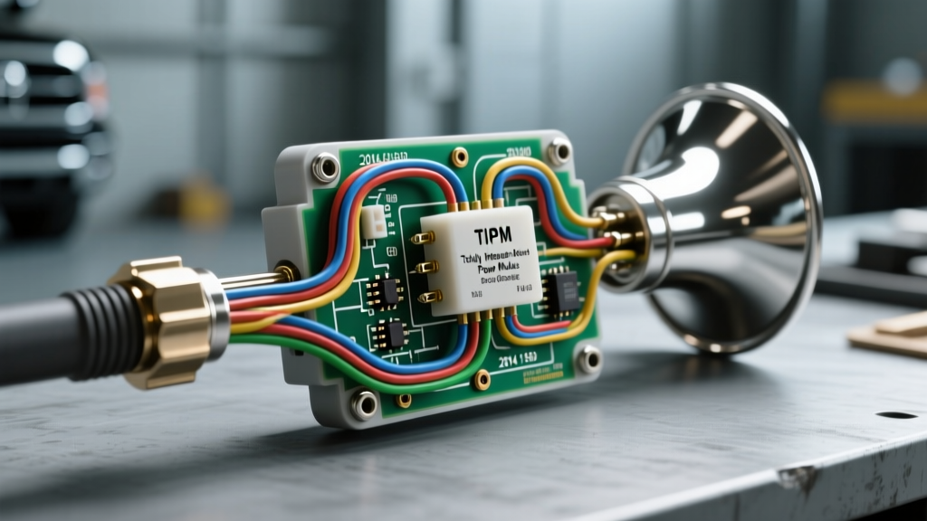
Introduction to the 2014 Ram 1500 Horn Circuit
The 4th-generation Ram 1500 (DS platform) utilizes a highly integrated, multiplexed electrical architecture. Unlike older vehicles where the horn button directly triggered a simple mechanical relay, the 2014 model relies on a complex network of modules. When troubleshooting a non-functional horn, accessing an accurate 2014 Ram 1500 horn wiring diagram is only the first step. Equally important is understanding the cost implications of module-level failures and possessing the correct diagnostic tools to isolate the fault without causing collateral damage to the vehicle's CAN bus network. This comprehensive guide breaks down the circuit architecture, outlines the exact tools required for professional-grade diagnostics, and provides a detailed cost analysis for both OEM and aftermarket repair strategies.
2014 Ram 1500 Horn Wiring Diagram & Circuit Architecture
The horn circuit in the 2014 Ram 1500 is not a simple hardwired loop; it is a logic-controlled system. The circuit begins at the steering wheel horn switch, which is a momentary ground switch. When depressed, it completes a ground path through the clockspring assembly to the Steering Column Control Module (SCCM). The SCCM interprets this ground signal and transmits a Controller Area Network (CAN) bus message to the Body Control Module (BCM). The BCM then sends a request to the Totally Integrated Power Module (TIPM) to energize the internal horn relay.
The TIPM houses the horn relay on its internal multi-layer printed circuit board (PCB). Once energized, the TIPM routes battery voltage (B+) through an internal 20A fuse out to the dual snail horn assembly located behind the front bumper grille. The most notorious failure point in this specific wiring diagram is the internal TIPM horn relay. Because the relay is surface-mounted and sealed within the TIPM, FCA's official dealership protocol dictates replacing the entire TIPM unit, which drastically inflates repair costs.
OEM Pinout and Wire Color Specification Chart
| Circuit Function | Wire Color (OEM) | AWG Size | Connector / Pin |
|---|---|---|---|
| Horn Switch Signal (Ground) | Dark Green/Orange (DG/OR) | 20 AWG | Clockspring C3, Pin 2 |
| Horn Feed (Left/Right Split) | Dark Green/White (DG/WT) | 16 AWG | TIPM C7 (Black), Pin 18 |
| Horn Assembly Ground | Black (BK) | 16 AWG | Chassis Ground G104 |
| CAN Bus High (SCCM to BCM) | Twisted Pair (Gray/White) | 22 AWG | SCCM C1, Pin 8 |
Essential Diagnostic Tools & Equipment Costs
Diagnosing multiplexed circuits requires precision. Piercing wire insulation with standard test lights or cheap multimeter probes violates SAE J1113 Electrical Testing Standards and introduces moisture into the harness, leading to galvanic corrosion and future CAN bus faults. To properly analyze the 2014 Ram 1500 horn wiring diagram in a real-world scenario, the following tools are mandatory:
- Automotive Multimeter (e.g., Fluke 87V): Required for measuring voltage drop across the TIPM C7 connector and verifying the integrity of the G104 chassis ground. A high-impedance meter prevents false readings on sensitive CAN bus lines. (Cost: ~$400)
- T-Pin Back-Probes (e.g., Pico TA010): Essential for safely probing the back of the TIPM and SCCM connectors without spreading the terminal pins or damaging the weather-pack seals. (Cost: ~$25)
- Power Probe IV (or equivalent): Allows the technician to inject 12V directly into the DG/WT horn feed wire at the TIPM connector, bypassing the vehicle's logic modules to instantly verify if the dual horn assembly and ground circuit are mechanically sound. (Cost: ~$550)
- Steering Column Trim Removal Kit: Nylon pry tools designed specifically to remove the SCCM shrouds and clockspring covers without snapping the brittle plastic tabs common on 2014 Ram interiors. (Cost: ~$30)
Repair Cost Analysis: OEM vs. Aftermarket Bypass Solutions
When the horn fails, the root cause is typically one of three components: the horn assembly itself, the clockspring, or the TIPM internal relay. Below is a cost breakdown comparing OEM replacement strategies versus expert-level bypass solutions.
| Component / Repair Strategy | OEM Part / Kit | Estimated Part Cost | Labor Time |
|---|---|---|---|
| Dual Horn Assembly (Mopar) | 68004153AA | $85.00 | 0.5 Hours |
| Clockspring Assembly (Mopar) | 68168259AB | $185.00 | 1.2 Hours |
| Complete TIPM Replacement (OEM) | 68071456AE | $1,150.00 | 1.5 Hours + Programming |
| External Relay Bypass Kit | Aftermarket Universal | $35.00 | 1.0 Hours |
As documented by Mopar Official Parts Catalog and independent specialists, replacing the TIPM solely for a horn relay failure is financially inefficient. The external relay bypass is the industry-preferred method for out-of-warranty vehicles, saving the owner over $1,000 while maintaining full horn functionality.
Common Failure Modes & Step-by-Step Bypass Procedure
Failure Mode 1: Internal TIPM Relay Burnout
The micro-ISO relay inside the TIPM is subjected to high inrush currents when the dual snail horns engage. Over time, the internal contacts pit and weld together, or the coil opens entirely. Because the TIPM is potted and sealed, the relay cannot be serviced conventionally. For deep-dive teardowns and PCB-level soldering instructions, resources like TIPM Rebuilders Horn Relay Bypass Guide offer excellent visual references, though most technicians opt for the external harness bypass.
Failure Mode 2: Clockspring Ribbon Tear
If the horn does not work, but the cruise control and steering wheel audio controls also exhibit intermittent faults, the clockspring flexible printed circuit (FPC) ribbon is likely torn. This requires replacing the clockspring and performing a steering angle sensor (SAS) recalibration via an advanced bi-directional scan tool.
Executing the External Relay Bypass (Bypassing the TIPM)
To bypass a failed internal TIPM horn relay without splicing into the delicate CAN bus network, follow this procedure:
- Disconnect the Battery: Isolate the negative terminal to prevent accidental airbag deployment or module shorts.
- Locate the Horn Feed: Identify the Dark Green/White (DG/WT) 16 AWG wire at the TIPM C7 connector, Pin 18. This is the output wire leading to the horns.
- Install the External Relay: Mount a standard 12V 40A SPST automotive relay in the engine bay, away from exhaust heat. Connect Terminal 30 to a fused 12V B+ source (use a 20A add-a-circuit in the under-hood fuse box).
- Wire the Load Circuit: Connect Terminal 87 of the external relay to the vehicle-side DG/WT wire using a 16-14 AWG heat-shrink butt splice. This will now feed power directly to the horns.
- Trigger the Relay: To trigger the relay (Terminal 86), you can tap the horn switch ground signal at the base of the steering column before it enters the SCCM, or use a scan tool to identify a BCM accessory output that triggers upon horn button actuation. Connect Terminal 85 to a clean chassis ground.
- Test and Seal: Reconnect the battery. Press the steering wheel horn pad. The external relay should click audibly, and the dual horns should sound. Apply dielectric grease to all splices and secure the harness with split-loom tubing.
Diagnostic Decision Tree
- Symptom: Horn does not sound, but clicking is heard from the TIPM.
Diagnosis: Horn assembly failure or corroded G104 ground. Check DG/WT wire for 12V at the horn connector during actuation. - Symptom: Horn does not sound, no clicking from TIPM, cruise control works.
Diagnosis: Internal TIPM relay failure or BCM logic fault. Proceed with external relay bypass. - Symptom: Horn does not sound, no clicking, cruise control/audio buttons also fail.
Diagnosis: Clockspring failure. Replace clockspring and recalibrate SAS.
Understanding the nuances of the 2014 Ram 1500 horn wiring diagram transforms a potentially catastrophic $1,200 dealership repair bill into a manageable, logical diagnostic procedure. By utilizing proper back-probing techniques and understanding the CAN bus architecture, technicians and advanced DIYers can accurately isolate faults and implement cost-effective, long-lasting solutions.