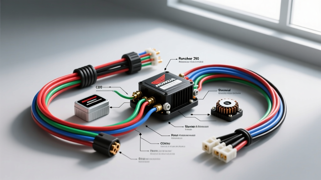
Why Upgrade the Honda Rancher 350 Ignition System?
The Honda TRX350 Rancher is a legendary workhorse, but its OEM electrical system was designed for stock lighting and basic starting loads. When you introduce high-draw LED light bars, heavy-duty winches, or performance CDI upgrades, the factory ignition wiring harness becomes a bottleneck. Voltage drop across undersized OEM wires and aging Sumitomo connectors can lead to weak sparks, hard starting, and melted stator plugs. Understanding the Honda Rancher 350 ignition wiring diagram is the first step toward building a bulletproof, modified electrical system capable of handling extreme trail and work conditions.
OEM Honda Rancher 350 CDI Pinout & Wire Colors
The TRX350 utilizes a Capacitor Discharge Ignition (CDI) system. Unlike Transistor Controlled Ignition (TCI) systems that rely on battery voltage and coil dwell time, the Rancher's CDI generates its own high-voltage spark energy using an internal capacitor charged by the stator's exciter coil. This means the CDI will fire even if the battery is completely dead, provided the engine is kicked or rolled over fast enough. Below is the factory CDI connector pinout and wire color mapping.
| CDI Pin | Wire Color | Function / Destination | Upgrade / Modification Notes |
|---|---|---|---|
| 1 | Black/Yellow | Ignition Kill Switch (Ground to stop) | Upgrade to marine-grade toggle; ensure zero resistance to ground when OFF. |
| 2 | Blue/Yellow | Pulse Generator (Pickup Coil) Signal | Shielded wire recommended if routing near high-amp winch cables. |
| 3 | Green | Chassis Ground | Scrape paint to bare metal; use star washer and dielectric grease. |
| 4 | Pink | Ignition Coil Primary (+) | Verify coil primary resistance (0.1 - 0.3 ohms) before upgrading. |
| 5 | Yellow/Red | Exciter Coil Power (from Stator) | Crucial for CDI capacitor charge; repair frayed wires immediately. |
Modification 1: High-Output Stator & Connector Upgrades
The most common failure point on the Honda Rancher 350 is the stator-to-harness connector. The OEM 3-phase AC output wires (Yellow) are typically 18 AWG, which is marginal for the amperage generated when charging a battery and running accessories. Over time, micro-corrosion increases resistance, generating enough heat to melt the plastic Sumitomo HM connector housing.
Step-by-Step Stator Harness Upgrade
- Cut the OEM Connector: Remove the factory 3-pin yellow stator plug. Leave enough wire on the stator side to work with, or repin the stator side if you have the proper Sumitomo extraction tool.
- Upsize the Wiring: Splice 14 AWG marine-grade tinned copper wire to the stator's Yellow output wires. According to SAE J1128 standards, 14 AWG wire can safely handle up to 35 amps in a bundle, far exceeding the Rancher's ~18-amp stator output.
- Install Deutsch DT Connectors: Crimp the new 14 AWG wires into a 3-pin Deutsch DT series connector. Use a proper quadlok crimp tool and seal the rear cavity with red polyurethane potting compound or hot melt to prevent moisture ingress.
- Heat Shrink Splices: Use 3M polyolefin adhesive-lined heat shrink (dual-wall) on all mid-harness splices. The inner adhesive melts and seals the wire strands, preventing the "green death" (copper oxidation) common in off-road environments.
Modification 2: Heavy-Duty Ignition & Accessory Busbar
When modifying the Rancher 350 for trail riding or farm work, you often need to tie accessories (GPS, radios, heated grips) into the ignition "Run" circuit. Tapping directly into the OEM ignition switch or the thin Black/Yellow CDI kill wire will overload the factory contacts, leading to voltage drop and switch failure. Instead, build a switched relay busbar.
The 40A Relay Busbar Build
By using a standard Bosch-style 5-pin 12V relay, you can use a low-amperage signal from the ignition switch to trigger a high-amperage power feed directly from the battery.
- Pin 30 (Input): Connect to the battery positive via a 40A inline fuse using 10 AWG red wire.
- Pin 87 (Output): Connect to a marine-grade terminal busbar. This busbar will power all your modified accessories.
- Pin 86 (Coil +): Tap into the OEM ignition switch "ON" output (typically Red/White or Black wire depending on the exact TRX350 year) using a Posi-Tap connector. Use 16 AWG wire.
- Pin 85 (Coil -): Connect to a clean chassis ground using 16 AWG green wire.
- Pin 87a: Not used for this application; tape off and secure.
This modification ensures your accessories receive full battery voltage (14.2V+ at idle) without pulling parasitic load through the fragile OEM ignition switch contacts. For complete marine and off-road wiring safety standards, refer to the ABYC E-11 Electrical Systems guidelines, which heavily influence best practices for DC relay isolation in wet environments.
Modification 3: Upgrading the Kill Switch & Tether Lanyard
The OEM handlebar kill switch on the Rancher 350 is a simple ground-interrupt circuit. When you press "OFF", the Black/Yellow wire from CDI Pin 1 is grounded, shorting the CDI's internal capacitor and preventing spark. For severe mud bogging or rock crawling, water ingress into the OEM plastic switch housing causes intermittent grounding, resulting in random engine misfires or complete stalling.
The Fix: Replace the OEM switch with a sealed, IP67-rated marine toggle switch. Wire the toggle switch in series with a magnetic engine shut-off tether lanyard. Run the new Black/Yellow wire through the steering column using a flexible braided sleeve to prevent chafing against the steel steering stem. Apply Nyogel dielectric grease inside the switch terminals to repel water and prevent galvanic corrosion between dissimilar metals.
Advanced Troubleshooting: Ignition & Stator Faults
Even with a modified harness, the TRX350's ignition components require specific clearances and resistances to function. Use this decision tree to diagnose no-spark conditions after performing wiring upgrades.
Symptom: Engine Cranks But No Spark
- Check 1: Kill Switch Circuit
- Disconnect the CDI plug. Set multimeter to continuity.
- Probe CDI harness Pin 1 (Black/Yellow) to chassis ground.
- If continuity exists with the key ON and kill switch set to RUN, you have a shorted kill switch, a pinched Black/Yellow wire, or a faulty ignition switch. Isolate and repair.
- Check 2: Pulse Generator (Pickup Coil)
- The pulse generator tells the CDI exactly when to fire the coil. If the air gap is too wide, the magnetic signal is too weak.
- Measure the gap between the pulse generator tip and the flywheel reluctor tooth using a brass feeler gauge. Spec: 0.020 to 0.035 inches.
- Test resistance across the Blue/Yellow and Green/Yellow wires at the harness. Should read between 90 - 110 ohms at 68°F (20°C). If open (OL), the pickup coil is dead.
- Check 3: Exciter Coil Output
- The exciter coil powers the CDI. Set your multimeter to AC Voltage.
- Probe the Yellow/Red wire at the stator while kicking the engine over.
- You should see a minimum of 15V AC. If voltage is low, the flywheel magnets may be demagnetized, or the stator exciter winding is shorted internally.
Symptom: Intermittent Misfire Under Load
If the Rancher bogs or misfires only when climbing hills or winching, suspect a voltage drop on the Pink ignition coil wire or a failing ignition coil. Under heavy vibration and heat, the internal epoxy of the OEM ignition coil can crack, causing the secondary winding to arc internally. Test the ignition coil secondary resistance by placing your multimeter probes on the spark plug boot terminal and the Pink wire terminal. A healthy OEM coil will read between 10,000 and 15,000 ohms. If it reads significantly higher, or fluctuates when tapped with a screwdriver handle, replace the coil and upgrade to a silicone-jacketed 8mm spark plug wire to prevent RF interference with aftermarket digital gauges.
Final Wiring Best Practices for the TRX350
When executing any modification based on the Honda Rancher 350 ignition wiring diagram, always disconnect the negative battery terminal first. Use a wire stripper that matches the AWG exactly (e.g., stripping 18 AWG wire with a 16 AWG blade will nick the copper strands, creating a weak point that will snap under ATV vibration). Finally, secure all modified harnesses using UV-resistant nylon cable ties and adhesive-backed wire loom clamps, keeping signal wires (Blue/Yellow) physically separated from high-current 10 AWG power feeds to prevent electromagnetic interference (EMI). For factory torque specs and component locations, always cross-reference your specific model year with the Honda Powersports Service Manuals.