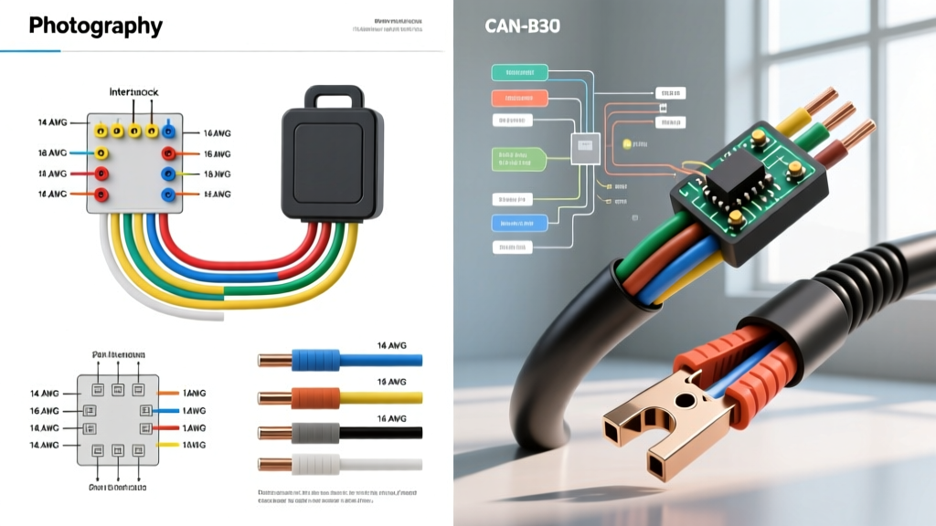
Understanding the Ignition Interlock Wiring Diagram Architecture
When integrating an Ignition Interlock Device (IID) into a vehicle's electrical system, technicians and advanced DIYers must navigate two distinctly different wiring architectures: the traditional analog starter interrupt and the modern CAN-bus data integration. Selecting the correct harness and referencing the accurate ignition interlock wiring diagram is critical not only for device functionality but for preserving the vehicle's immobilizer system and avoiding parasitic draws. According to the NHTSA Ignition Interlock Guidelines, improper installation can lead to false lockouts, stalling while driving, or damage to the vehicle's Body Control Module (BCM). This guide compares the wiring requirements, harness selection criteria, and technical specifications for both architectures.
Architecture 1: Analog Starter Interrupt (Relay-Based)
For vehicles manufactured prior to 2012, or heavy-duty commercial trucks with conventional starter circuits, the IID utilizes a physical starter interrupt. The core of this ignition interlock wiring diagram revolves around a standard ISO mini relay (Bosch-style 5-pin). The IID head unit acts as a switch, providing a ground path to the relay coil only when the breath alcohol concentration (BrAC) is below the programmed threshold (typically 0.02% to 0.04%).
Analog Relay Pinout & Wire Gauge Specifications
When building or selecting an analog interrupt harness, wire gauge and insulation type must meet SAE J1128 standards for under-hood heat resistance. GXL or TXL cross-linked polyethylene insulation is mandatory to withstand 125°C continuous operating temperatures.
- Pin 30 (Common / Ignition 12V+): Sourced from the ignition switch "Start" position. Wire: 16 AWG TXL, Red.
- Pin 87 (Normally Open / Starter Solenoid Out): Routes to the starter solenoid "S" terminal. Wire: 16 AWG TXL, Yellow.
- Pin 87a (Normally Closed / Starter Solenoid In): Spliced into the OEM starter signal wire coming from the ignition switch or clutch/brake safety switch. Wire: 16 AWG TXL, White.
- Pin 86 (Coil 12V+): Tapped to a fused 12V ignition source. Wire: 18 AWG GXL, Red.
- Pin 85 (Coil Ground / IID Control): Connects directly to the IID harness control wire. The IID provides the ground path to energize the coil. Wire: 18 AWG GXL, Black.
Architecture 2: Modern CAN-Bus Data Integration
Vehicles manufactured from 2015 onward utilize multiplexed Controller Area Network (CAN) systems. Cutting the starter signal wire on a modern Ford, GM, or Chrysler vehicle will often trigger a U0100 (Lost Communication with ECM) or U0140 (Lost Communication with BCM) diagnostic trouble code, and may permanently lock the anti-theft system. For these vehicles, the ignition interlock wiring diagram shifts from physical high-current switching to low-voltage data sniffing and BCM gateway integration.
CAN-Bus Wiring Specifications
CAN-bus integration modules read the "Ignition ON" and "Engine RUN" status directly from the OBD-II port or the BCM gateway connector. The IID then communicates with a proprietary bypass module that safely requests starter enablement via the data bus.
- CAN-High (CAN-H): Typically Pin 6 on the OBD-II J1939/J1962 connector. Wire: 22 AWG Twisted Pair, White or White/Red.
- CAN-Low (CAN-L): Typically Pin 14 on the OBD-II connector. Wire: 22 AWG Twisted Pair, White/Blue or Green.
- Termination Resistance: The CAN network requires a 120-ohm termination resistor at each end of the bus. Integration harnesses must not alter this resistance. Always verify network health with an oscilloscope; CAN-H should idle at 2.5V and peak at 3.5V, while CAN-L should idle at 2.5V and drop to 1.5V.
For deeper network topology references, technicians should consult the SAE J1939 standard documentation regarding heavy-duty and light-duty CAN-bus voltage thresholds.
Universal Ignition Interlock Harness Comparison Table
| Feature | Analog Starter Interrupt Harness | CAN-Bus Data Integration Harness |
|---|---|---|
| Primary Connection Point | Ignition Switch Harness / Starter Relay | OBD-II Port / BCM Gateway Connector |
| Starter Wire Modification | Physical Cut & Splice (Series Interrupt) | None (Data Request via BCM) |
| Wire Gauge Requirements | 16 AWG (High Current), 18 AWG (Coil) | 22 AWG (Data), 18 AWG (Power/Ground) |
| Immobilizer Interaction | High Risk (PATS/Passlock disruption) | Low Risk (Reads transceiver data passively) |
| Typical Installation Time | 45 - 90 Minutes | 20 - 40 Minutes |
Vehicle-Specific Selection: Navigating Immobilizer Systems
Selecting the correct wiring diagram and harness requires identifying the vehicle's specific anti-theft architecture. Disturbing the wiring harness near the steering column can trigger immobilizer lockouts if not handled correctly.
Ford PATS (Passive Anti-Theft System)
Ford vehicles utilize a transceiver ring around the ignition cylinder that reads a passive RFID chip in the key. If an analog IID harness requires removing the steering column shrouds and zip-tying the IID control box near the column, the physical proximity of the IID's internal magnets or speakers can interfere with the PATS transceiver field. Selection Guide: Always use a CAN-bus integration module for Ford vehicles 2011+ to avoid column teardowns. If an analog harness must be used, the IID control module must be mounted at least 12 inches away from the PATS transceiver ring.
GM Passlock & Pass-Key III
Older GM vehicles (1998-2010) use the Passlock system, which embeds a Hall-effect sensor and a specific resistance resistor in the ignition lock cylinder. Cutting the yellow Passlock data wire to install an IID starter interrupt will result in a "Starting Disabled" message and a 10-minute security lockout. Selection Guide: For Passlock vehicles, the ignition interlock wiring diagram must include a Passlock bypass module that learns the resistance value, or the installer must tap the starter solenoid wire after the PCM/BCM security relay, rather than at the ignition switch.
Termination & Splicing Standards for IID Harnesses
The Haynes Automotive Electrical Manual strictly advises against the use of "T-taps" or "scotch locks" for any ignition or data circuit. These connectors pierce the wire insulation, exposing the copper strands to galvanic corrosion and increasing the risk of voltage drop, which can cause the IID head unit to randomly reboot and lock the driver out.
- Power & Ground (12V/18 AWG): Use military-style Western Union splices, soldered with rosin-core solder, and sealed with 3M dual-wall adhesive-lined heat shrink (shrinks at 125°C, melts adhesive at 85°C).
- CAN-Bus Data (22 AWG): Must be spliced using the "Y-splice" method to maintain the twisted-pair geometry. Untwisting the CAN-H and CAN-L wires by more than 1 inch will cause electromagnetic interference (EMI) and data packet loss, resulting in intermittent IID communication failures.
- Fuse Tapping: For constant 12V memory and ignition sense lines, always use an "Add-a-Circuit" (Mini or ATO) fuse tap at the interior fuse box. Never wrap wires around fuse legs or use fuse-slot blades without proper strain relief.
Troubleshooting Common IID Wiring Faults
When the vehicle exhibits starting anomalies post-installation, use this diagnostic decision tree to isolate the wiring fault:
- Symptom: Engine cranks but will not start; Security light flashing.
- Cause: IID harness was spliced into the fuel pump relay or immobilizer data line instead of the starter solenoid signal.
- Fix: Verify wiring diagram. Move the Pin 87/87a splice to the low-current starter trigger wire at the PCM or ignition switch.
- Symptom: IID head unit powers on, but vehicle will not crank even after passing breath test.
- Cause: Voltage drop across the relay coil ground (Pin 85). The IID's internal transistor cannot sink enough current to ground due to a poor chassis ground connection.
- Fix: Clean chassis ground point to bare metal. Apply dielectric grease and torque ground bolt to 8 Nm (71 lb-in).
- Symptom: IID displays "Communication Error" or "Sync Failed" on CAN-bus vehicles.
- Cause: CAN-H and CAN-L wires are reversed, or the twisted pair was separated too far during splicing.
- Fix: Verify Pin 6 (CAN-H) and Pin 14 (CAN-L) continuity. Re-splice maintaining the twist rate of 1 twist per inch.
Final Selection Verdict
For any vehicle manufactured after 2012, a CAN-bus data integration harness is the superior choice. It eliminates the need to cut high-current starter circuits, preserves the OEM warranty, and prevents immobilizer conflicts. However, for classic cars, heavy-duty diesel trucks, and older analog platforms, a meticulously soldered 5-pin relay analog harness remains the industry standard. Always cross-reference your specific vehicle's factory service manual pinout before cutting or splicing any wires.