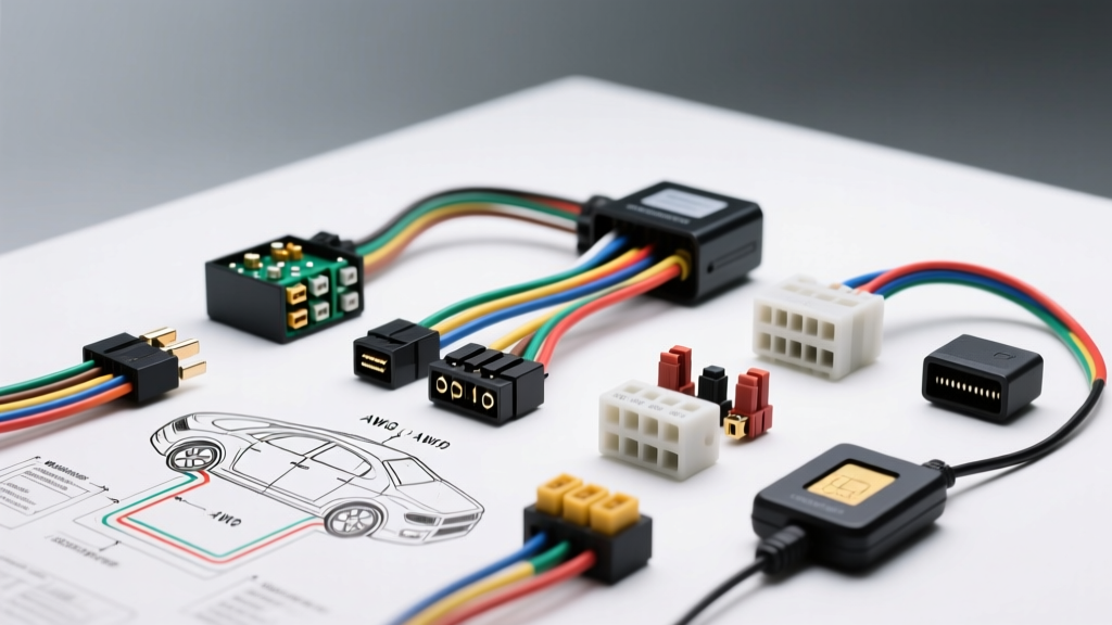
The Reality of Fleet Immobilizer Installations
Securing commercial fleets, military transport, and high-value utility vehicles often requires integrating an HID (High-Frequency Identification) proximity card reader with the vehicle's ignition immobilizer system. Unlike static building access control, automotive environments subject these readers to extreme voltage fluctuations, electromagnetic interference (EMI), and high-amperage inductive loads. Referencing an accurate HID card reader wiring diagram is only the first step; understanding the underlying automotive electrical architecture is what separates a secure fleet from a yard full of bricked vehicles.
This guide dissects the most critical safety warnings, pinout specifications, and catastrophic wiring mistakes made when adapting HID card readers for 12V DC vehicle applications.
Critical Safety Warnings Before Tapping Vehicle Harnesses
SRS Airbag and CAN Bus Interference
Modern commercial vans (such as the Ford Transit and Ram ProMaster) route high-speed CAN bus networks and SRS (Supplemental Restraint System) wiring through the lower A-pillars and kick panels—exactly where HID readers are typically mounted. Never use 'T-tap' or 'scotch-lock' splice connectors. These puncture the wire insulation, exposing copper to moisture and causing galvanic corrosion. More dangerously, a stray strand of copper from a damaged SRS squib wire can bridge into your HID reader's ground path, potentially deploying an airbag or triggering a permanent SRS fault code.
- Battery Protocol: Disconnect the negative battery terminal and wait a minimum of 15 minutes for the SRS backup capacitors to discharge before cutting or stripping any wires under the dash.
- Splicing Standard: Use only soldered connections sealed with dual-wall, adhesive-lined polyolefin heat shrink tubing to maintain the OEM harness's environmental seal and vibration resistance.
Analyzing the HID Card Reader Wiring Diagram: Pinout & Specs
Below is the standard 7-pin wiring schematic for a heavy-duty 12V DC automotive HID immobilizer reader. Adhering to SAE J1292 Automobile Wiring Color Codes and proper AWG sizing is mandatory to prevent voltage drops and logic board failures.
| Pin | Wire Color | AWG Size | Function / Connection Point | Fusing / Notes |
|---|---|---|---|---|
| 1 | Red | 12 AWG | +12V Constant Battery Power | Inline 15A ATO Fuse (within 6 inches of source) |
| 2 | Black | 12 AWG | Chassis Ground | M6 Ring Terminal, Torque to 7-10 Nm on bare metal |
| 3 | Yellow | 16 AWG | Starter Relay Control Intercept (Input) | Splice into OEM Crank Signal wire (Ignition Switch side) |
| 4 | Blue | 16 AWG | Starter Relay Control Intercept (Output) | Routes to OEM Starter Relay Coil (Engine side) |
| 5 | White | 18 AWG | Ignition 'Run' Sense | Connect to OEM IGN1 circuit (Active only in Run/Start) |
| 6 | Green | 18 AWG | Door Ajar / Hood Trigger | Connect to OEM Dome Light trigger (Negative switching) |
| 7 | Violet | 20 AWG | Status LED / Buzzer Output | Max 500mA draw; use relay for high-wattage alarms |
Top 5 Installation Mistakes and How to Fix Them
Mistake 1: Intercepting the High-Amp Solenoid Wire
The Error: Installers frequently confuse the starter relay control wire with the heavy-gauge wire running directly from the battery to the starter solenoid. The solenoid wire (typically 8 AWG or 4 AWG) carries 40+ amps during cranking. The HID reader's internal PCB relay is usually rated for only 10A continuous. Intercepting the solenoid wire will instantly melt the reader's internal traces and potentially cause an under-dash electrical fire.
The Fix: Always intercept the starter relay control circuit. Use a digital multimeter (DMM) to locate the wire that shows +12V only when the key is held in the 'Crank' position. This wire is typically 16 AWG or 18 AWG and carries less than 3 amps, safely within the HID reader's relay limits.
Mistake 2: Omitting Flyback Snubber Diodes
The Error: When the HID reader's internal relay opens to interrupt the starter circuit, the collapsing magnetic field of the vehicle's OEM starter relay coil generates an inductive voltage spike (back-EMF). This spike can exceed 100V, traveling backward into the HID reader and frying its microcontroller or Wiegand data lines.
The Fix: Solder a 1N4007 flyback diode (1000V, 1A) directly across the coil pins of the vehicle's OEM starter relay, or across the HID reader's Yellow and Blue output wires. Ensure the diode's cathode ring (stripe) faces the +12V ignition side. This clamps the voltage spike safely to ~0.7V, protecting the reader's logic board.
Mistake 3: Parasitic Draw from Constant 12V Polling
The Error: Wiring the HID reader's main power to a constant +12V source without utilizing the 'Ignition Sense' (White) wire. Many older or poorly designed readers continuously poll for a card at full power (drawing 150mA - 300mA). Left unattended over a weekend, this parasitic draw will drain a standard 80Ah commercial battery below the threshold required to crank a diesel engine.
The Fix: Ensure the White (Ignition Sense) wire is connected to a true IGN1 circuit. Program the reader's firmware to enter 'Ultra-Low Sleep Mode' (<2mA draw) whenever the ignition sense wire drops to 0V for more than 5 minutes. Reference the Bosch Automotive Electrics guidelines for acceptable parasitic draw thresholds on commercial chassis.
Mistake 4: Improper Grounding to Painted Chassis
The Error: Securing the Black (Ground) 12 AWG wire to a painted seat belt anchor or using a self-tapping screw into a coated frame rail. During engine cranking, system voltage can drop to 9.5V. If the ground connection has a resistance of just 0.5 ohms due to paint or rust, the voltage drop will cause the HID reader's microprocessor to brown-out and reboot. If the reader reboots while the driver is cranking, the starter circuit will be interrupted, leading to a no-crank condition and potential starter gear damage.
The Fix: Use an M6 or M8 ring terminal. Sand the chassis mounting point down to bare, shiny metal using 80-grit sandpaper. Secure the bolt with a star lock washer, torque to 7-10 Nm, and coat the entire terminal in dielectric grease to prevent future oxidation. Verify the ground with a voltage drop test; it must read less than 0.1V under load.
Mistake 5: Splicing into Data Lines Instead of Hardwired Relays
The Error: Attempting to integrate the HID reader directly into the vehicle's J1939 or high-speed CAN bus network by splicing into the twisted-pair data lines to mimic an OEM immobilizer transponder signal. CAN bus networks operate on strict 120-ohm impedance and differential voltage tolerances. Splicing into these wires introduces capacitance and impedance mismatches, throwing U-codes (e.g., U0100 Lost Communication with ECM) and putting the vehicle into a permanent limp-home mode.
The Fix: Unless you are using a specialized CAN bus translator module, keep the HID card reader isolated from the data network. Rely strictly on analog hardwired relay interrupts (Starter and Fuel Pump) to secure the vehicle. If fuel pump interruption is required, locate the fuel pump relay control wire in the rear fuse block or kick panel and intercept it using the same 16 AWG methodology as the starter circuit.
Testing and Validation Protocols
Before reassembling the dash panels, perform a rigorous validation sequence. First, test the immobilizer state with an unauthorized card: verify 0V on the Blue (Starter Out) wire when the key is turned to 'Crank'. Next, test with an authorized card: verify +12V on the Blue wire during cranking. Finally, simulate a voltage drop using a carbon pile load tester on the battery while polling a valid card to ensure the HID reader's internal voltage regulator maintains logic stability down to 8.5V. Adhering to these standards and referencing proper NFPA 70 / NEC Article 511 guidelines for commercial garage electrical modifications ensures your fleet security system is both impenetrable and electrically sound.