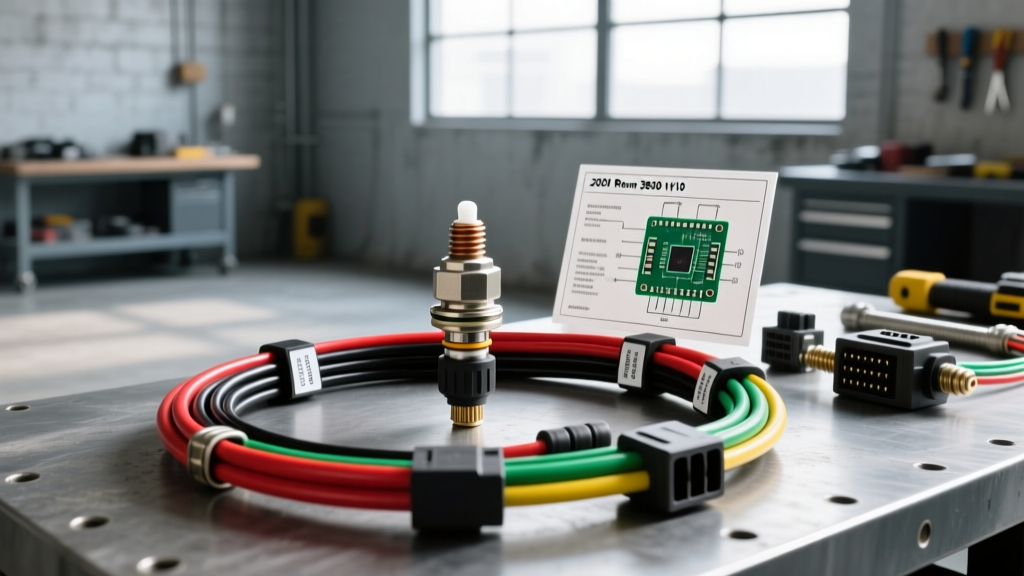
Understanding the 8.0L V10 JTEC O2 Sensor Network
The 2001 Dodge Ram 3500 equipped with the 8.0L Magnum V10 is a heavy-duty workhorse that demands precise fuel delivery. To manage the air/fuel ratio across ten massive cylinders, Chrysler utilized the JTEC (Jeep/Truck Engine Controller) PCM paired with a four-sensor heated zirconia oxygen (O2) network. Unlike smaller engines, the V10 generates extreme under-hood and exhaust manifold temperatures, making the oxygen sensor wiring harness highly susceptible to thermal degradation, chafing, and vibration-induced fatigue.
When replacing a failed sensor or repairing a melted pigtail on the 2001 Ram 3500 V10, relying on generic splice kits will inevitably lead to recurring P0130-P0167 diagnostic trouble codes (DTCs). This practical how-to installation guide provides the exact 2001 Ram 3500 V10 engine oxygen sensor wiring diagram data, PCM pinouts, and military-grade splicing techniques required to survive the harsh V10 environment.
O2 Sensor Locations and Bank Identification
Before cutting into the harness, you must correctly identify the sensor banks. On the 8.0L V10:
- Bank 1 (Driver Side): Contains Cylinder 1. Bank 1 Sensor 1 (B1S1) is upstream of the catalytic converter; Bank 1 Sensor 2 (B1S2) is downstream.
- Bank 2 (Passenger Side): Contains Cylinder 2. Bank 2 Sensor 1 (B2S1) is upstream; Bank 2 Sensor 2 (B2S2) is downstream.
2001 Ram 3500 V10 Engine Oxygen Sensor Wiring Diagram Data
The 2001 JTEC PCM utilizes three main connectors: C1 (Black, 32-way), C2 (White, 32-way), and C3 (Gray, 32-way). The O2 sensor signal and ground circuits route primarily through the C2 connector, while the heater circuit relies on the Automatic Shutdown (ASD) relay for power and a dedicated chassis ground. Below is the definitive wiring reference chart for the 8.0L V10.
| Sensor ID | Function | Wire Color (OEM) | AWG | PCM Connector & Pin |
|---|---|---|---|---|
| B1S1 | Signal Output | Dark Green / Light Blue | 18 AWG | C2, Pin 24 |
| B2S1 | Signal Output | Dark Green / Orange | 18 AWG | C2, Pin 25 |
| B1S2 | Signal Output | Tan / White | 18 AWG | C2, Pin 4 |
| B2S2 | Signal Output | White / Dark Green | 18 AWG | C2, Pin 5 |
| All Sensors | Signal Ground (Low Noise) | Black / Light Blue | 18 AWG | C1, Pin 4 (Common) |
| All Sensors | Heater Feed (ASD Relay) | Dark Green / Orange (Tracer) | 16 AWG | Fused B+ (Not PCM) |
| All Sensors | Heater Ground | Black / White | 16 AWG | Chassis Ground G100 |
Practical Harness Repair and Sensor Installation Guide
Replacing the sensor is only half the battle. On a 2001 V10, the wiring harness often becomes brittle from decades of heat cycling. Follow these steps to ensure a permanent repair.
Step 1: Safely Depower and Access the PCM
- Disconnect the Battery: Always isolate the negative battery terminal. The JTEC PCM remains active for several minutes after key-off, and back-probing live O2 signal wires can fry the internal PCM A/D converters.
- Locate the PCM: The JTEC module is mounted in the engine bay on the passenger side firewall. Unbolt the three connectors (C1, C2, C3) to verify pin integrity. Look for green copper oxide corrosion on Pin 24 and 25 of the C2 connector, a common failure point that mimics a bad O2 sensor.
Step 2: Military-Grade Splicing (Solder vs. Crimp)
The 8.0L V10 produces severe low-frequency vibrations. Standard butt-crimps will work-harden and snap within 10,000 miles. You must use a soldered, adhesive-lined heat shrink method.
- Strip the Wires: Use precision wire strippers to remove exactly 3/8 inch of insulation from the 18 AWG signal wires and 1/2 inch from the 16 AWG heater wires. Never use a razor blade, which nicks the copper strands and creates a stress riser.
- Stagger the Splices: Do not align the cut points of all four wires. Stagger them by at least 1 inch to prevent a bulky, single-point harness bulge that can snag on debris.
- Western Union Splice & Solder: Twist the stripped wires in a tight Western Union (Lineman) splice. Apply 60/40 rosin-core solder until the joint wicks completely. Never use acid-core plumbing solder.
- Dual-Wall Heat Shrink: Slide 3:1 shrink ratio, marine-grade adhesive heat shrink over the joint. The inner adhesive melts and seals out moisture and road salt, while the outer jacket provides abrasion resistance.
Step 3: Sensor Threading and Torque Specifications
When installing the new 4-wire Metri-Pack 280 sensor into the exhaust manifold or pipe:
- Apply a thin layer of copper-based anti-seize to the M18x1.5 threads. Keep the compound strictly below the first thread to prevent poisoning the zirconia sensor element.
- Thread the sensor in by hand to avoid cross-threading the cast iron manifold.
- Use a specialized O2 sensor socket and a torque wrench to tighten to 30 lb-ft (40 Nm). Over-torquing can crack the ceramic sensing element inside the steel shell.
Troubleshooting Common V10 O2 Circuit Failures
If you have installed the sensor and repaired the wiring but the Check Engine Light persists, use this diagnostic decision tree tailored to the 2001 JTEC architecture.
Symptom: Heater Circuit Codes (P0135, P0141, P0155, P0161)
Cause: The PCM monitors the O2 heater circuit by checking for a voltage drop. If the circuit is open, or if the current draw is outside the 1.5A to 3.0A expected range, it sets a code.
- Check the ASD Relay: The Dark Green/Orange heater feed wire is powered by the Automatic Shutdown (ASD) relay. If the ASD relay is faulty, none of the O2 heaters will receive 12V. Test for 12V at the heater feed wire with the Key On, Engine Off (KOEO).
- Verify Ground G100: The Black/White heater ground wire routes to chassis ground G100, located near the passenger side cylinder head. Remove the bolt, sand the mounting surface to bare metal, and re-torque to 10 lb-ft.
Symptom: Signal Circuit Codes (P0130, P0150) or Stuck at 0.45V
Cause: The signal wire is shorted to ground, shorted to the heater circuit, or the low-noise signal ground is compromised.
- Test Signal Ground: Back-probe the Black/Light Blue wire at the sensor connector. Measure resistance to the negative battery terminal. It must read less than 0.5 ohms. If higher, the PCM internal ground or the C1 Pin 4 wire is compromised.
- Check for Cross-Shorts: Due to harness melting near the V10 exhaust manifolds, the 12V heater feed often melts into the 0-1V signal wire. This will instantly destroy the JTEC PCM's internal O2 driver. Inspect the harness where it crosses the rear of the passenger side cylinder head.
Authoritative References
For further diagnostic procedures and OEM specifications, consult the following industry-standard resources:
- SAE J1979: E/E Diagnostic Test Modes - Society of Automotive Engineers (Defines OBD-II O2 sensor monitoring protocols and PID definitions).
- Mopar OEM Wiring Schematics - Stellantis/Mopar (Official reference for JTEC PCM pinouts and ASD relay routing).
- Haynes Dodge Ram Pick-Up Repair Manual (2001) - Haynes Manuals (Provides chassis-specific ground locations and torque specifications for the 8.0L V10).
By adhering to the exact wire colors, AWG requirements, and JTEC PCM pinouts outlined in this 2001 Ram 3500 V10 engine oxygen sensor wiring diagram guide, you will eliminate phantom drivability issues and ensure your heavy-duty truck runs at peak efficiency.