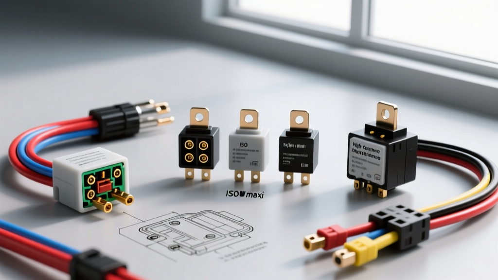
Introduction to Automotive Relay Selection
When adding high-draw accessories like off-road LED light bars, electric fuel pumps, or high-amperage cooling fans to your vehicle, running the power directly through a dashboard switch is a recipe for melted wiring and electrical fires. This is where the automotive relay becomes the unsung hero of your electrical system. However, selecting the correct component requires a deep understanding of the standard car relay diagram. Whether you are upgrading a classic muscle car or modifying a modern overland rig, misinterpreting relay pinouts or choosing the wrong suppression type can lead to catastrophic ECU damage or immediate component failure.
In this comprehensive product comparison and selection guide, we will decode the universal DIN 72552 terminal standards, compare 4-pin versus 5-pin ISO configurations, and provide actionable wiring schematics to ensure your next electrical project is safe, efficient, and built to last.
The Standard Bosch ISO Pinout: Decoding the Numbers
Before comparing specific relay products, you must understand the nomenclature used in almost every OEM and aftermarket car relay diagram. The industry relies on the DIN 72552 standard to label relay terminals. Regardless of the manufacturer—be it Bosch, Littelfuse, or Hella—the numbers stamped on the relay base remain consistent.
| Terminal ID | Function | Typical Wire Gauge (AWG) | Standard Aftermarket Wire Color |
|---|---|---|---|
| 30 | Common Input (Battery 12V+) | 10 AWG or 12 AWG | Red |
| 87 | Normally Open (NO) Output | 10 AWG or 12 AWG | Blue or Yellow |
| 87a | Normally Closed (NC) Output | 10 AWG or 12 AWG | Green (or absent on 4-pin) |
| 86 | Coil Power (Trigger 12V+) | 18 AWG or 16 AWG | White |
| 85 | Coil Ground | 18 AWG or 16 AWG | Black |
Note: In OEM car relay diagrams, wire colors will vary wildly by manufacturer (e.g., GM often uses Pink/Black or Dark Blue, while Ford utilizes Yellow/Light Green). Always trace the circuit or use a multimeter to verify OEM wire functions before splicing.
Product Comparison: 4-Pin vs. 5-Pin ISO Mini Relays
The ISO Mini relay is the most ubiquitous component in modern automotive fuse boxes. They typically measure 1.0 x 1.0 x 0.6 inches and are rated for 30 to 40 Amps. However, choosing between a 4-pin and a 5-pin variant dictates how your circuit behaves.
4-Pin SPST (Single Pole Single Throw)
The 4-pin relay acts as a simple remote-controlled on/off switch. When the coil (Pins 85 and 86) is energized, the internal contactor bridges Pin 30 to Pin 87.
- Best Applications: Electric fuel pumps, radiator cooling fans, off-road lighting, and horn upgrades.
- Diagram Logic: Power flows from the battery (via a fuse) to Pin 30. When the dash switch sends 12V to Pin 86, and Pin 85 is grounded, the circuit closes, sending power out of Pin 87 to the load.
- Selection Tip: If your car relay diagram only requires a simple high-amperage trigger, a 4-pin SPST is the most reliable choice due to its simpler internal contactor mechanism.
5-Pin SPDT (Single Pole Double Throw)
The 5-pin relay includes an additional terminal: 87a. In its resting state, Pin 30 is connected to Pin 87a (Normally Closed). When energized, the connection breaks from 87a and bridges to Pin 87 (Normally Open).
- Best Applications: Headlight upgrades (switching from low to high beam), power window polarity reversal, and alarm system immobilizer circuits.
- Diagram Logic: Allows a single relay to control two separate circuits or reverse the polarity of a DC motor by routing Pin 87 to positive and Pin 87a to negative (or vice versa) across the motor terminals.
- Selection Tip: Never use a 5-pin relay as a direct substitute for a 4-pin relay in high-vibration environments without capping the 87a terminal. An exposed 87a terminal can cause a dead short if it accidentally contacts the vehicle chassis.
High-Current Applications: When to Upgrade to ISO Maxi
While the ISO Mini is rated for 30A-40A, continuous loads (like a massive winch solenoid or a 60A electric power steering pump) will cause the internal contacts of a Mini relay to arc, pit, and eventually weld shut. For these applications, you must consult a car relay diagram that specifies an ISO Maxi or ISO 280 heavy-duty relay.
ISO Maxi relays feature larger contact surfaces, heavier copper windings, and are typically rated for 50A to 70A continuous duty. They utilize wider 0.250-inch spade terminals compared to the 0.187-inch terminals found on Mini relays. When wiring an ISO Maxi, you must upgrade your Pin 30 and Pin 87 wiring to 8 AWG and utilize a high-amperage MIDI or ANL fuse directly at the battery.
Internal Protection: Diode vs. Resistor Relays
One of the most critical, yet overlooked, aspects of reading a car relay diagram is identifying the required flyback voltage suppression. When the 12V trigger is removed from the relay coil, the collapsing magnetic field generates an inductive voltage spike (often exceeding 300V). If your relay is triggered by a modern ECU, PCM, or Body Control Module (BCM), this spike will instantly destroy the solid-state driver transistor.
According to SAE J284 standards regarding automotive relay testing, suppression is mandatory for module-driven circuits. You have two product choices:
- Resistor Suppressed Relays: Contain an internal parallel resistor. They dissipate the spike as heat. Advantage: Polarity insensitive (you can wire 85 and 86 either way). Disadvantage: Slower coil collapse time.
- Diode Suppressed Relays: Contain an internal reverse-biased diode. Advantage: Fastest coil collapse, safest for sensitive ECUs. Disadvantage: Polarity Sensitive. Pin 85 must be ground, and Pin 86 must be 12V+. Reversing these will bypass the diode and fry your ECU.
Always check the OEM car relay diagram. If the schematic shows a diode symbol across the coil, you must purchase a diode-suppressed replacement and verify coil polarity before applying power.
Real-World Wiring Guide: Sizing Wires and Fuses
Selecting the right relay is only half the battle. The Painless Performance Wiring manual emphasizes that wire gauge must be sized based on the total amperage draw and the length of the wire run to prevent voltage drop. Below is a quick reference chart for the high-amperage load side (Pins 30 and 87) of your car relay diagram:
| Load Amperage | Wire Length (Under 10 ft) | Wire Length (10 ft - 20 ft) | Recommended Fuse |
|---|---|---|---|
| 10A - 15A | 14 AWG | 12 AWG | 15A or 20A ATO |
| 20A - 30A | 12 AWG | 10 AWG | 30A ATO |
| 40A - 50A | 10 AWG | 8 AWG | 50A MIDI |
| 60A+ | 8 AWG | 6 AWG | 70A ANL |
Troubleshooting Common Relay Failures
Even with a perfect car relay diagram, real-world conditions introduce failure points. Here is how to diagnose the most common automotive relay issues using a digital multimeter (DMM):
- Melted Connector Housing (Pin 30): This is rarely a relay failure; it is a terminal tension failure. If the female spade connector on your wiring harness is loose, it creates high electrical resistance. Under a 30A load, this resistance generates massive heat, melting the plastic ISO socket. Fix: Never reuse melted pigtails. Cut, crimp on new high-quality brass terminals, and apply dielectric grease.
- Coil Resistance Out of Spec: Set your DMM to Ohms (Ω) and probe Pins 85 and 86. A healthy 12V ISO Mini relay should read between 60 and 90 Ohms. If it reads infinite (OL), the internal copper winding is broken. If it reads near 0, the coil is shorted.
- Voltage Drop Across Contacts: With the relay energized and the load running, measure DC voltage between Pin 30 and Pin 87. A healthy relay will show a voltage drop of less than 0.1V. If you read 0.5V or higher, the internal contactor is pitted from arcing and the relay must be replaced.
Final Selection Verdict
When sourcing components based on your car relay diagram, always prioritize sealed, weather-resistant ISO relays (often marked with an IP67 or IP6K9K rating) for any application located in the engine bay or under the chassis. For interior or fuse-box applications, standard open-frame ISO Mini relays are perfectly adequate. By matching the correct pinout (4-pin vs 5-pin), verifying the suppression type (Diode vs Resistor), and sizing your wiring correctly, you ensure a robust electrical system capable of handling the harshest automotive environments.
For further technical specifications on contact materials and lifecycle testing, refer to the Littelfuse Automotive Relay catalog to cross-reference OEM part numbers with high-quality aftermarket equivalents.