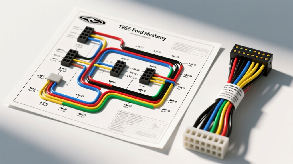
1966 Mustang Electrical Architecture: The Alternator Transition
The 1966 Ford Mustang represents a pivotal transition year in early pony car electrical architecture. Unlike the 1964.5 and 1965 models, which predominantly relied on DC generators, the 1966 model year standardized the Motorola 1G alternator across most V8 and inline-six configurations. This shift fundamentally altered the engine bay wiring harness, requiring new routing for the voltage regulator and specific gauge cluster feedback loops. For restorers and technicians utilizing a 66 Mustang wiring diagram, understanding the divergence between the early generator harness and the late-model alternator harness is critical to preventing catastrophic electrical fires and ensuring proper charging system operation.
Furthermore, 1966 introduced federal safety mandates that affected the wiring schematic, most notably the integration of the neutral safety switch (NSS) on automatic transmission models, and the standardization of the emergency flasher circuit. This technical specification reference breaks down the primary harness routing, wire gauge requirements, and connector pinouts specific to the 1966 model year.
Main Dash & Headlight Harness Color Codes
Ford utilized a standardized color-coding system in the mid-1960s, relying on a base color with a contrasting stripe (tracer) to denote specific circuits. The main dash harness and headlight harness in the 1966 Mustang utilize SAE J1128 compliant low-tension primary cable, typically featuring cross-linked polyethylene (XLPE) insulation for high-temperature resistance near the firewall and exhaust manifolds. Below is the primary circuit reference chart for the forward lighting and dash power feeds.
| Circuit Function | Base / Tracer Color | AWG Size | Routing & Termination |
|---|---|---|---|
| Main Battery Feed | Black / Yellow | 10 AWG | Battery Pos to Ammeter Shunt / Starter Solenoid |
| Headlight Power Feed | Red / Black | 12 AWG | Headlight Switch to Floor Dimmer Switch |
| Right Front Turn Signal | White / Blue | 14 AWG | Turn Signal Flasher to RH Front Lamp |
| Left Front Turn Signal | Green / White | 14 AWG | Turn Signal Flasher to LH Front Lamp |
| Ignition Switch Output | Red / Green | 14 AWG | Ignition Switch to Coil (+) and Voltage Regulator |
| Horn Relay Ground | Yellow / Black | 16 AWG | Steering Column Horn Ring to Horn Relay Coil |
| Tail / Parking Lights | Brown | 14 AWG | Headlight Switch to Rear Lamp Harness Bulkhead |
Engine Bay: The 1G Alternator & Voltage Regulator Pinout
The most significant wiring change for the 1966 Mustang was the adoption of the Autolite/Motorola 1G alternator. This required a dedicated alternator harness that routed from the 1G alternator plug to the fender-mounted mechanical voltage regulator. The voltage regulator utilizes a 4-pin Packard 56 series connector. Incorrect pinning here is the leading cause of overcharging and melted harnesses in restored 66 Mustangs.
Voltage Regulator Connector Specifications
- Pin A (Alternator): Black/Orange (10 AWG). Routes directly to the alternator output stud. This provides the primary charging current to the battery and ammeter shunt.
- Pin S (Stator): White (14 AWG). Connects to the alternator stator tap. This signal tells the regulator the alternator is spinning and generating AC voltage, which is also used to extinguish the dash 'GEN' or 'ALT' indicator light.
- Pin I (Ignition): White (14 AWG). Receives switched 12V from the ignition switch. This energizes the regulator's internal contact points when the key is in the 'Run' position.
- Pin F (Field): Yellow (14 AWG). Routes to the alternator field terminal. The regulator pulses the ground path on this wire to control the alternator's rotor excitation and overall voltage output.
When referencing a factory Fordification 64-66 wiring schematic, note that early 1966 build dates may still feature generator-style wiring if the vehicle was equipped with the base inline-six and dealer-installed generator delete options, though this is exceptionally rare. Always verify the physical alternator plug (a 3-wire molded pigtail, though often wired as a 2-wire with a jumper loop) before repinning the regulator side.
The 1966 Neutral Safety Switch (NSS) Integration
Prior to 1966, Mustangs with automatic transmissions (C4) could be cranked in any gear. Federal safety standards mandated the introduction of the Neutral Safety Switch for the 1966 model year. The NSS is located on the side of the C4 transmission case and interrupts the starter solenoid engagement circuit unless the selector is in Park or Neutral.
The wiring routing for the NSS is as follows: The Red/Light Blue (14 AWG) wire exits the ignition switch in the 'Start' position and travels down the steering column to the NSS multi-plug. After passing through the NSS contacts, the wire transitions to Red/Blue (12 AWG) and routes through the firewall bulkhead connector to the 'S' terminal on the starter solenoid. If your 1966 Mustang cranks in gear, inspect the NSS multi-plug for backed-out terminals or a bypassed jumper wire, a common hack used by previous owners when the internal switch contacts corrode.
Common Failure Modes & Restoration Troubleshooting
When working with 50-year-old copper and degraded PVC/XLPE insulation, specific failure modes are virtually guaranteed on the 1966 Mustang platform. Addressing these during a harness restoration or repair is mandatory for vehicle safety.
1. The Ammeter Shunt Fire Hazard
The 1966 Mustang dash cluster features an ammeter that measures current flow to and from the battery. Unlike modern shunt-type ammeters, the Ford design routes the actual heavy-gauge charging current (up to 40 amps) through the back of the dash gauge via a heavy copper shunt loop. The connection points on the back of the ammeter are isolated from the metal dash bezel by fragile fiber washers. If these washers crack or are omitted during cluster restoration, the heavy-gauge Black/Yellow power feed shorts directly to the grounded metal dash. This results in an immediate, un-fused dead short that will melt the main harness and ignite the under-dash insulation. Always upgrade to a modern external shunt ammeter or a voltmeter conversion kit when rebuilding a 66 Mustang gauge cluster.
2. Headlight Switch Thermal Overload
The factory headlight switch contains an internal bimetallic thermal circuit breaker. The headlight circuit on the 1966 Mustang is not protected by a standard glass fuse in the fuse block; it relies entirely on this switch. When owners upgrade to high-draw halogen sealed beams without installing a dedicated headlight relay harness, the increased amperage causes the thermal breaker to cycle. The symptom is headlights that randomly turn off after 5 minutes of driving, then turn back on once the switch cools. According to Hemmings First-Generation Mustang wiring guides, the proper repair is not a replacement switch, but the installation of a 30-amp Bosch-style relay harness triggered by the factory Red/Black headlight feed wire.
3. Bulkhead Connector Corrosion
The main firewall bulkhead connector on the driver's side fender apron is highly susceptible to water ingress. The 1966 design lacks a robust silicone weather seal compared to later decades. Corrosion on the 14 AWG and 12 AWG terminals increases resistance, leading to voltage drop at the taillights and dim headlights. When repinning this connector, use authentic Ford-spec Packard 56 series terminals with the correct crimp dies, and pack the connector cavity with dielectric grease to prevent future galvanic corrosion.
Wire Gauge and SAE Compliance Notes
When sourcing replacement wire for a 66 Mustang harness rebuild, adherence to SAE J1128 Low Tension Primary Cable standards is highly recommended. The original Ford harness used stranded copper with a nominal strand count of 19 to 41 depending on the AWG. Using modern, cheap automotive wire with fewer strands and thicker, brittle insulation will result in wire fatigue and breakage inside the loom, particularly in the flexible hinges of the doors and the steering column drop loop. Always specify GXL or TXL cross-linked wire for engine bay harnesses to withstand the 125°C ambient temperatures near the 289ci V8 exhaust manifolds.