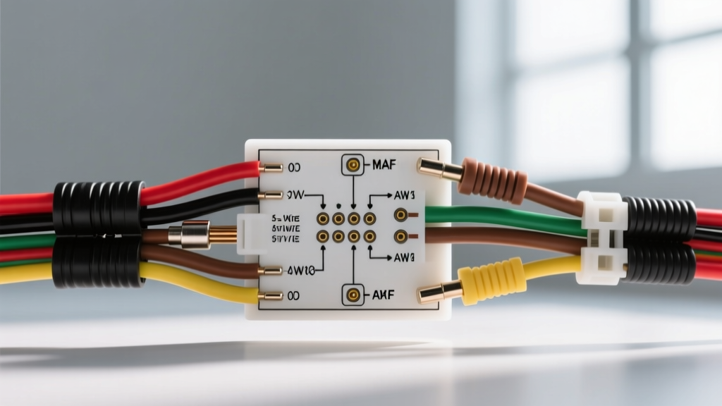
Decoding the 5 Wire Mass Air Flow Sensor Wiring Diagram
When upgrading an engine management system or performing a complex engine swap, understanding the correct sensor integration is critical for optimal fueling and ignition timing. Modern powertrains frequently utilize a combined Mass Air Flow (MAF) and Intake Air Temperature (IAT) sensor housed in a single unit. This requires a specific 5 wire mass air flow sensor wiring diagram to properly route power, grounds, and dual signal circuits back to the Powertrain Control Module (PCM). Unlike older 3-wire MAF setups, the 5-pin configuration integrates a dedicated thermistor circuit for the IAT, demanding precise attention to wire gauge, shielding, and pinout sequencing to prevent electromagnetic interference (EMI) and signal degradation.
Standard 5-Pin MAF/IAT Connector Pinout
The following table outlines the standard pinout for a common Bosch/Hitachi-style 5-wire MAF/IAT sensor found in many late-model GM and Ford applications. Always verify against your specific factory service manual, but this configuration serves as the industry baseline for aftermarket harness fabrication.
| Pin | Function | Typical Wire Color | AWG Size | Circuit Type |
|---|---|---|---|---|
| A | 12V Ignition Power | Pink / Red | 18 AWG | Switched Battery Voltage |
| B | MAF Signal Output | Green / White | 20 AWG | Analog Voltage or Frequency |
| C | Sensor Ground (MAF) | Black | 20 AWG | Low-Current Ground Return |
| D | IAT Signal Output | Yellow | 22 AWG | 5V Reference Pull-Down |
| E | IAT Low Reference | Black / White | 22 AWG | PCM Dedicated Sensor Ground |
Essential Tools and Connector Specifications
Before beginning the physical installation, you must source the correct automotive-grade materials. Using standard hardware store wire and butt connectors will inevitably lead to resistance buildup, galvanic corrosion, and catastrophic signal noise. According to SAE J1128 Low Tension Primary Cable standards, under-hood wiring must utilize cross-linked polyethylene (XLPE) insulation, specifically GXL or TXL wire, to withstand 125°C to 150°C ambient engine bay temperatures.
For the sensor side, you will need a 5-way weather-sealed connector. The industry standard is the Aptiv GT150 connector series (formerly Delphi), which utilizes open-barrel crimp terminals and silicone secondary locks. You will also need an open-barrel crimping tool (such as a Titan T4480 or equivalent), a wire stripper calibrated for 18-22 AWG, and dual-wall adhesive-lined heat shrink tubing.
Step-by-Step MAF/IAT Harness Installation
Step 1: Wire Selection and AWG Matching
Cutting corners on American Wire Gauge (AWG) sizing is the most common cause of MAF-related drivability issues. The 12V ignition feed (Pin A) requires 18 AWG wire to prevent voltage drop under high electrical load conditions. If the voltage at the sensor drops below 11.5V, the internal MAF bridge circuit will under-report airflow, causing the PCM to pull fuel and create a dangerous lean condition at wide-open throttle (WOT). The signal wires (Pins B and D) should be 20 AWG or 22 AWG. Using wire that is too thick for signal circuits makes routing difficult and can damage the delicate internal sensor pins due to excessive mechanical leverage and vibration.
Step 2: Routing and EMI Shielding
The MAF signal wire (Pin B) is highly susceptible to Electromagnetic Interference (EMI). If this wire is routed parallel to ignition coil harnesses, fuel injector circuits, or alternator output cables, the induced voltage spikes will mimic erratic airflow readings, resulting in idle surge and hesitation. Route the MAF signal wire at least four inches away from high-current or high-frequency switching wires. If crossing high-voltage wires is unavoidable, do so at a strict 90-degree angle. For forced-induction or high-output ignition setups, encase the MAF and IAT signal wires in a tinned copper braided shield. Ground the shield to the engine block at one end only to prevent ground loops.
Step 3: Terminal Crimping and Weather Sealing
Proper crimping is non-negotiable. Strip exactly 3mm of insulation from the GXL wire. Place the Aptiv GT150 terminal into the open-barrel crimper. The crimp must exhibit a visible 'bellmouth' at the front of the wire grip to prevent the sharp edge of the terminal from shearing copper strands over time. The insulation grip must securely bite into the wire jacket without piercing it. Slide the yellow silicone weather seal over the wire before crimping, ensuring it seats fully into the rear cavity of the terminal. Once all five pins are crimped, insert them into the 5-way housing until the locking tang clicks. Insert the secondary Terminal Position Assurance (TPA) lock to guarantee the pins cannot back out under engine vibration.
Step 4: PCM Pinout Integration
At the PCM end, you must identify the specific pins for the MAF signal, IAT signal, and the dedicated IAT low-reference ground. Never splice the IAT Low Reference (Pin E) into the main MAF Sensor Ground (Pin C) or the engine block ground. The PCM uses a dedicated 5-voltage-drop reference circuit for the IAT thermistor. Sharing a ground with the high-current MAF heater or bridge circuit will introduce a floating ground offset, causing the PCM to read inaccurate intake temperatures. Follow Haynes electrical system basics and wiring tutorials for proper PCM pin extraction and insertion techniques to avoid damaging the delicate ECU header.
Post-Installation Multimeter Diagnostics
Once the harness is routed and connected, perform a static diagnostic test before starting the engine. Turn the ignition to the 'ON' position (engine off). Using a digital multimeter (DMM) and fine T-pins to backprobe the connector, verify that Pin A reads within 0.2V of battery voltage. Next, backprobe Pin D (IAT Signal); it should read between 2.5V and 4.0V depending on ambient air temperature. Finally, verify continuity between Pin C and Pin E back to their respective PCM ground pins to ensure no open circuits exist in the harness.
Common Wiring Failure Modes and Fixes
Even with a perfect 5 wire mass air flow sensor wiring diagram, execution errors can cause hidden faults. Use this decision tree to diagnose post-installation anomalies.
| Symptom | Probable Wiring Cause | Corrective Action |
|---|---|---|
| IAT reads -40°F / -40°C constantly | Open circuit on IAT Signal (Pin D) or IAT Low Ref (Pin E). | Check continuity from sensor connector to PCM. Look for a pushed-back pin in the GT150 housing. |
| MAF reading drops or flattens at high RPM | Voltage drop on 12V Ignition feed (Pin A) due to undersized wire or poor crimp. | Load-test the 12V circuit with a headlight bulb. Upgrade to 16 AWG if voltage drops below 11.5V under load. |
| Erratic MAF readings at idle; engine surges | EMI interference on MAF Signal (Pin B) from ignition coils or alternator. | Reroute the signal wire away from noise sources. Apply braided shielding grounded at the PCM end. |
| IAT reading drifts higher as engine bay heats up | Sensor ground (Pin C) shared with a high-current accessory, causing thermal resistance. | Isolate Pin C and run a dedicated 20 AWG ground wire directly to the PCM sensor ground bus. |
By adhering strictly to these wire gauge specifications, crimping methodologies, and routing protocols, your 5-wire MAF/IAT installation will provide the PCM with the pristine, noise-free data required for precise fuel mapping and optimal engine performance.