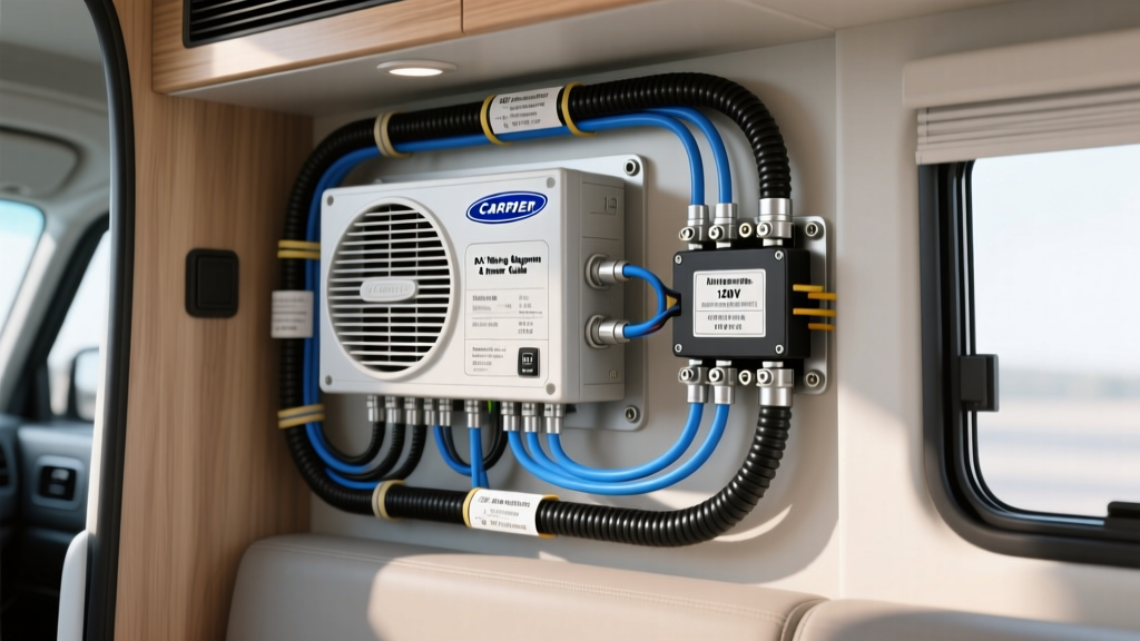
Adapting the Carrier AC Unit Wiring Diagram for Motorhome and RV Applications
Integrating a residential-grade HVAC system into a Class A motorhome, custom Sprinter camper van, or skoolie conversion requires a deep understanding of both automotive DC electrical systems and residential 120V AC architecture. While standard rooftop RV air conditioners rely on simple 30-amp twist-lock receptacles, utilizing a high-efficiency residential compressor means you must interpret a standard carrier ac unit wiring diagram and adapt it for a mobile, vibration-heavy environment powered by inverters, generators, and shore power. This technical specification reference details the exact wire gauges, terminal pinouts, and Automatic Transfer Switch (ATS) logic required to safely run a Carrier 1.5-ton or 1-ton ductless or window-style unit off an automotive lithium battery bank and pure sine wave inverter.
Primary Power Terminal Block: 120V AC Input Specifications
Unlike factory-installed RV units, a residential Carrier AC requires hardwiring into the vehicle's AC distribution panel or a dedicated inverter sub-panel. The main power terminal block on the Carrier outdoor/indoor air handler typically accepts 115V/120V single-phase power for units under 1.5 tons. When referencing the carrier ac unit wiring diagram for the main power whip, you must adhere to NFPA 70 (NEC) Article 551 standards for Recreational Vehicles, which mandate strict grounding and overcurrent protection protocols.
Main Power Terminal Pinout and Wire Color Codes
| Terminal Designation | Function | Standard Wire Color | Minimum AWG (Up to 20ft) | Breaker Size |
|---|---|---|---|---|
| L1 (Hot) | 120V AC Line Input | Black | 10 AWG THHN | 30A |
| N (Neutral) | AC Return Path | White | 10 AWG THHN | N/A |
| GND (Ground) | Equipment Grounding | Bare Copper / Green | 10 AWG THHN | N/A |
Expert Note: In an automotive or RV environment, voltage drop over long wire runs is a critical failure point. If your inverter is located in the rear garage of a motorhome and the Carrier air handler is in the front bedroom, you must step up to 8 AWG stranded copper wire to mitigate voltage drop below 3%. Compressors experiencing a voltage drop below 108V will draw excessive amperage, overheat the thermal overload protector, and prematurely fail the run capacitor.
Thermostat Control Wire Pinouts and Low-Voltage Logic
The low-voltage control circuit is where most automotive-to-residential retrofit errors occur. The carrier ac unit wiring diagram utilizes standard 24V AC control logic, which requires a dedicated step-down transformer (usually built into the air handler) to convert 120V AC to 24V AC. When wiring a smart RV thermostat or a standard 5-wire HVAC thermostat, use 18 AWG 5-conductor stranded thermostat wire to resist chassis vibration.
24V Control Board Terminal Strip
- R (Red): 24V AC Hot from transformer. Powers the thermostat logic.
- C (Blue/Black): 24V AC Common. Essential for Wi-Fi smart thermostats and completing the control relay circuit.
- Y (Yellow): Compressor Contactor Coil. Energizes the outdoor condenser unit.
- G (Green): Blower Motor Relay. Engages the indoor air handler fan.
- W (White): Heating Element / Reversing Valve (if equipped with auxiliary heat strips).
Inverter Sizing and Automatic Transfer Switch (ATS) Logic
Running a Carrier compressor off an automotive alternator and lithium battery bank requires managing Locked Rotor Amps (LRA). A standard 1.5-ton Carrier compressor may have a Rated Load Amp (RLA) draw of 12A, but an LRA surge of up to 65A upon startup. A standard 2000W inverter will immediately trip its overcurrent protection. To resolve this, RV integrators utilize a 3000W+ Pure Sine Wave Inverter paired with a soft-start module (such as the MicroAir EasyStart 364), which reduces the LRA surge by up to 70%.
ATS Relay Integration for Generator and Shore Power
When wiring the Carrier unit into the RV's Automatic Transfer Switch, the ATS must prioritize power sources to prevent backfeeding the inverter or shore power pedestal. The ATS uses 12V DC trigger wires from the RV's central monitoring panel to switch heavy-duty 120V AC relays.
| ATS Trigger Source | 12V DC Trigger Wire Color | Relay State | Priority Level |
|---|---|---|---|
| Shore Power (30A/50A) | Red | Normally Closed (NC) | Priority 2 |
| Onan/Cummins Generator | Yellow | Normally Open (NO) | Priority 1 |
| Inverter / Battery Bank | Blue | Normally Open (NO) | Priority 3 |
Chassis Grounding and Bonding Requirements
A frequent and dangerous mistake in skoolie and camper van conversions is failing to bond the residential AC ground to the vehicle chassis. According to NFPA 70: National Electrical Code (NEC) Article 551.54, the grounding terminal of the RV's AC distribution panel must be bonded to the vehicle's metal chassis. When installing the Carrier AC unit, the bare copper ground wire from the terminal block must be routed to a dedicated, star-washed grounding lug bolted directly to the steel chassis frame. This ensures that in the event of a compressor short-to-case, the fault current has a low-impedance path back to the source, tripping the 30A breaker instantly rather than electrifying the RV's exterior skin.
Real-World Failure Modes and Voltage Drop Diagnostics
Even with a perfectly executed carrier ac unit wiring diagram, mobile environments introduce unique failure modes. Use this diagnostic tree when troubleshooting system faults:
Symptom: Compressor Hums but Fails to Start (Thermal Overload Trips)
- Cause 1: Voltage drop across the 120V AC wiring harness. Fix: Measure AC voltage at the Carrier contactor while the compressor attempts to start. If voltage drops below 108V, upgrade the supply wiring from 10 AWG to 8 AWG and check battery inverter cable crimps.
- Cause 2: Inverter output waveform distortion. Fix: Verify the inverter is outputting a True Pure Sine Wave. Modified Sine Wave inverters will cause the Carrier compressor windings to overheat and the run capacitor to explode due to harmonic distortion.
Symptom: Smart Thermostat Loses Wi-Fi Connection Intermittently
- Cause 1: Missing 'C' wire connection. Fix: Ensure the 18 AWG Blue wire is securely terminated at both the Carrier control board 'C' terminal and the thermostat baseplate. Power stealing from the 'Y' wire is insufficient in high-vibration environments.
- Cause 2: 24V transformer vibration failure. Fix: Check the 40VA 24V step-down transformer mounted inside the air handler. Ensure it is secured with RTV silicone or rubber isolation mounts to prevent solder joint fractures on the PCB.
Authoritative References and Further Reading
For complete schematics and safety compliance, always cross-reference your specific model's documentation and national electrical codes:
- NFPA 70: National Electrical Code (NEC) - Article 551 (Recreational Vehicles and Recreational Vehicle Parks)
- Carrier Residential HVAC Installation and Service Manuals
- RV Industry Association (RVIA) Electrical Systems Standards
By treating the residential carrier ac unit wiring diagram not as a static home blueprint, but as a dynamic mobile schematic subject to vibration, voltage variance, and DC-to-AC inversion, you can build an ultra-reliable, off-grid capable climate control system for any automotive or RV platform.