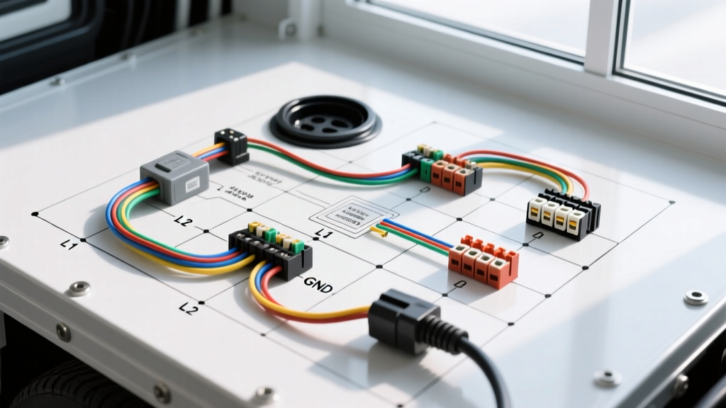
High-Draw Auxiliary Power in Mobile Service Trucks and Custom Rigs
When outfitting a heavy-duty mobile service truck, expedition motorhome, or custom mobile welding rig with 240V auxiliary power, technicians frequently search for a wiring diagram for 3 prong dryer plug setups. The NEMA 10-30 configuration, historically used in residential electric dryers, provides 240 volts at 30 amps. In the automotive upfitting world, this specific high-amperage architecture is often repurposed to feed onboard AC/DC stick welders, heavy-duty rotary screw air compressors, and high-draw plasma cutters mounted in the service bodies of mobile mechanic trucks. However, adapting residential electrical standards to a mobile, high-vibration, dual-voltage (12V/24V DC and 120V/240V AC) environment requires rigorous adherence to automotive electrical safety protocols. While a standard residential electrician might simply wire a NEMA 10-30 receptacle to a breaker panel, an automotive electrical engineer must account for chassis vibration, thermal derating in engine bays, and strict AC/DC ground isolation to prevent catastrophic failure or fatal shock hazards.
Understanding the NEMA 10-30 Configuration in Automotive Environments
The NEMA 10-30 is a 3-wire, 240V, 30A configuration consisting of two hot legs (X and Y) and a combined neutral/ground (W). In modern residential applications, this has been largely superseded by the 4-prong NEMA 14-30, which separates the neutral and equipment grounding conductor. However, many legacy mobile welders and heavy-duty industrial compressors still utilize the 3-prong NEMA 10-30P plug. When integrating this into a mobile service truck, the primary challenge is the absence of a dedicated ground wire. In a stationary home, the neutral is bonded to the ground at the main service panel. In a vehicle, the steel chassis serves as the DC return path (ground). Bonding the AC neutral of a NEMA 10-30 to the vehicle chassis is strictly prohibited by NFPA 70 (National Electrical Code) Article 551 regarding recreational and mobile units, as a floating neutral can energize the entire truck frame with 120V/240V AC current, posing a lethal shock hazard and causing rapid AC electrolysis on the vehicle's suspension and drivetrain components.
Pinout and Terminal Mapping for Vehicle Integration
Below is the terminal mapping for integrating a NEMA 10-30 inlet receptacle into a mobile service body's auxiliary AC distribution panel. This assumes the use of an isolated AC sub-panel where the AC neutral bus is strictly isolated from the DC chassis ground bus.
| Terminal ID | Standard Wire Color | Electrical Function | Vehicle Integration & Isolation Protocol |
|---|---|---|---|
| X (Hot 1) | Black | 120V AC Leg 1 | Routed to Pole 1 of a 30A HACR-rated double-pole breaker. |
| Y (Hot 2) | Red | 120V AC Leg 2 | Routed to Pole 2 of the double-pole breaker (180° out of phase). |
| W (Neutral) | White | Combined Neutral/Ground | Must terminate on an ISOLATED AC neutral bus bar. Never bond to the truck chassis or DC negative bus. |
| Chassis | Green/Bare | Vehicle DC Ground | The inlet's metal mounting flange must be grounded to the service body via a dedicated 8 AWG green grounding strap. |
Step-by-Step Installation Guide for Mobile Rigs
Step 1: Wire Sizing and AWG Selection
For a 30A continuous load, the NEC dictates a minimum of 10 AWG copper wire. However, mobile service trucks subject wiring to extreme thermal environments, especially when routed near diesel particulate filters (DPF), exhaust aftertreatment systems, or hydraulic PTO lines. Standard THHN wire is insufficient for under-chassis routing. Instead, automotive upfitters should utilize SAE J1128 compliant SXL (Cross-Linked Polyethylene) wire or high-temperature silicone jacketed cable. If routing 10 AWG SXL through high-heat zones (ambient temperatures exceeding 105°C / 221°F), you must upsize to 8 AWG to compensate for thermal derating and prevent voltage drop, which can severely damage the diodes in onboard welding rectifiers.
Step 2: Routing, Conduit, and Vibration Damping
Unlike stationary residential wiring, a mobile rig experiences constant high-frequency vibration and chassis torsion. All 240V AC wiring must be routed through flexible, non-metallic liquid-tight conduit to protect against abrasion from sharp steel service body edges. Where the conduit passes through the floor of the service body or the chassis frame rails, use heavy-duty rubber grommets sealed with automotive-grade polyurethane seam sealer to prevent water ingress and exhaust soot contamination. Secure the conduit every 12 inches using UV-resistant, stainless-steel cushion clamps (P-clamps) lined with EPDM rubber to absorb harmonic vibration and prevent the conduit from sawing through mounting brackets over thousands of miles of travel.
Step 3: Termination and Torque Specifications
Vibration is the enemy of electrical connections. Standard residential wire nuts are strictly prohibited in mobile environments. All terminations inside the auxiliary distribution panel must be made using DIN-rail mounted terminal blocks (such as Phoenix Contact or Weidmuller) or heavy-duty ring terminals crimped onto the wire ends. Use a Mil-Spec compliant crimping tool (e.g., M22520/2-01) to ensure a cold-weld crimp, followed by adhesive-lined, dual-wall heat shrink tubing. The heat-activated adhesive creates a waterproof seal that prevents moisture-induced corrosion. When tightening the terminal screws on the NEMA 10-30 inlet and the double-pole breaker, use a calibrated torque screwdriver. Most 30A terminal blocks require between 15 and 20 in-lbs of torque. Under-torquing leads to arcing and melted housings; over-torquing strips the brass threads or shears the screw head.
Troubleshooting Common High-Draw Vehicle Electrical Failures
Even with a flawless wiring diagram for 3 prong dryer plug configurations, mobile environments introduce unique failure modes. Below is a diagnostic decision tree for common issues encountered in mobile welding and compressor setups:
- Symptom: Welder arcs erratically or compressor motor hums but fails to start under load.
Cause: Severe voltage drop across the AC hot legs due to undersized wiring or loose terminal connections.
Fix: Measure voltage at the inlet and at the welder receptacle simultaneously while under load. If the drop exceeds 3% (approx. 7.2V on a 240V circuit), inspect all crimped ring terminals for micro-fractures and verify that 10 AWG wire was not substituted with 12 AWG. - Symptom: The truck's 12V DC electronics (ECU, infotainment, LED lighting) experience interference, flickering, or premature failure.
Cause: AC neutral-to-chassis bonding. The high-draw AC load is bleeding harmonic noise and return current onto the vehicle's DC ground plane.
Fix: Immediately isolate the AC sub-panel neutral bus. Verify with a multimeter that there is infinite resistance (OL) between the AC neutral bus and the vehicle's DC negative battery terminal/chassis ground. - Symptom: NEMA 10-30 plug melts or shows severe thermal discoloration at the X or Y prongs.
Cause: The mobile welder is drawing sustained amperage exceeding the 30A rating of the plug, or the female inlet contacts have lost tension due to vibration.
Fix: Check the welder's duty cycle and primary amperage draw. If the equipment requires 40A+ for specific automotive frame-straightening or heavy-gauge welding tasks, the entire system must be upgraded to a 50A NEMA 6-50 or 14-50 configuration using 6 AWG wire.
Safety, Grounding, and Code Compliance
Integrating high-voltage AC into a steel vehicle chassis requires meticulous attention to grounding. While the NEMA 10-30 lacks a dedicated equipment grounding conductor in its plug design, the metal inlet receptacle mounted to the service body must still be grounded. This is achieved by bonding the metal inlet housing to the service body's AC ground bus using a short, 8 AWG green jumper wire. The service body's AC ground bus must then be bonded to the vehicle chassis using a single, heavy-gauge bonding strap. This ensures that if a hot wire chafes and shorts to the metal service body, the fault current has a low-impedance path back to the source, tripping the double-pole breaker instantly. For comprehensive guidelines on mobile power integration, refer to the Lincoln Electric Mobile Welding Guidelines, which detail the specific harmonic filtering and grounding requirements for operating transformer-based and inverter-based welding equipment on mobile generators and shore-power inlets. By treating the wiring diagram for 3 prong dryer plug setups not as a simple residential task, but as a complex mobile electromechanical integration, automotive upfitters can ensure reliable, safe, and code-compliant high-draw power for any job site.