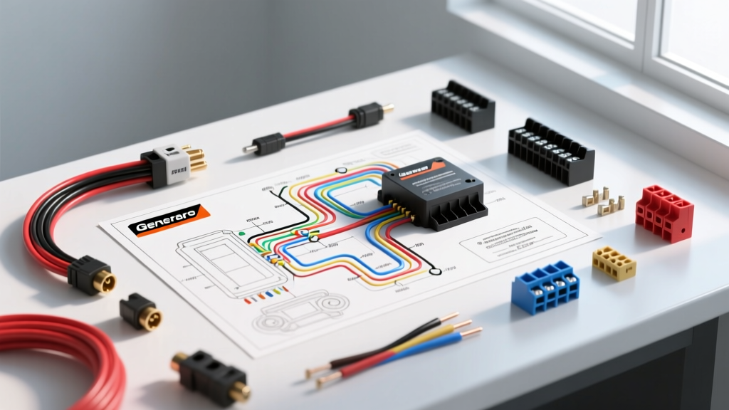
Upgrading Mobile Command and Class A RV Power Systems
When upfitting a heavy-duty Class A motorhome, an F-550 expedition command vehicle, or a mobile medical unit, managing dual high-amperage AC power sources is critical. Standard 50A RV transfer switches are insufficient for rigs running dual roof AC units, residential refrigerators, and 120V server racks. This is where integrating a residential-grade heavy-duty switch becomes necessary. When technicians search for a Generac 200 amp automatic transfer switch wiring diagram PDF, they are typically looking at residential standby applications. However, adapting this diagram for a mobile, high-vibration vehicle chassis requires a deep understanding of automotive electrical isolation, DC-to-AC control logic, and severe-duty wire routing.
In a mobile command center, Source 1 (Utility) is typically mapped to a 20kW PTO-driven onboard generator, while Source 2 (Generator) is mapped to a massive 4000W+ Lithium-Ion Inverter/Charger bank. The Generac RTSW200A3 is an excellent candidate for this upgrade due to its robust contactors, but the factory wiring schematic must be heavily modified to survive the automotive environment.
Adapting the Generac 200 Amp Automatic Transfer Switch Wiring Diagram PDF for Vehicle Chassis
The official Generac 200 amp automatic transfer switch wiring diagram PDF assumes a static concrete pad, rigid conduit, and a stable 120/240V split-phase utility grid. In an expedition truck, the "utility" is subject to voltage sags during engine cranking, and the chassis experiences continuous torsional flex. The primary adaptation involves replacing the residential 120V AC sensing lines (N1 and N2) with a 12V DC automotive relay logic system to prevent high-voltage AC from running through the vehicle's thin-wall control harnesses.
12V DC Control Logic vs. Residential 120V AC Sensing
The Generac ATS controller uses the N1 and N2 lines to sense the presence of AC voltage before closing the contactors. Running 120V AC sensing wires through a vehicle's frame rail alongside 12V DC CAN bus networks is a recipe for electromagnetic interference (EMI) and catastrophic short circuits. Instead, we use a galvanic isolation relay setup.
- Step 1: Install a 12V DC to 120V AC micro-inverter (pure sine wave) dedicated solely to the ATS logic board.
- Step 2: Use the vehicle's Battery Management System (BMS) and PTO ignition sense circuits to trigger Bosch-style 12V 40A relays.
- Step 3: These relays switch the micro-inverter's output into the N1 and N2 terminals on the Generac logic board, tricking the ATS into believing the grid or generator is present based on 12V DC ignition states.
Wire Gauge, Routing, and Chassis Grounding Specifications
Handling 200 amps of continuous AC load in a mobile environment requires strict adherence to SAE J1128 standards for battery and primary cables. Standard residential THHN wire pulled through PVC conduit will fracture under chassis vibration. You must use SGT (Starter Gauge Thermoplastic) fine-strand marine wire, which features up to 426 individual 30 AWG strands per 2/0 cable, providing the flexibility needed to absorb engine harmonics and frame twist.
| Terminal / Connection | Wire Gauge (AWG) | Wire Type | Torque Specification | Hardware / Lug Type |
|---|---|---|---|---|
| Source 1 (PTO Gen) Main Lugs | 2/0 AWG | SGT Fine-Strand | 180 in-lbs (15 ft-lbs) | Closed-End Copper, 3/8" stud |
| Source 2 (Inverter) Main Lugs | 2/0 AWG | SGT Fine-Strand | 180 in-lbs (15 ft-lbs) | Closed-End Copper, 3/8" stud |
| Load (Main Distribution Panel) | 2/0 AWG | SGT Fine-Strand | 180 in-lbs (15 ft-lbs) | Closed-End Copper, 3/8" stud |
| Chassis Ground (Neutral Bond) | 4 AWG | SGT Fine-Strand | 90 in-lbs | Ring Terminal, 5/16" bolt to frame |
| N1/N2 Control Logic Harness | 14 AWG | TXL Cross-Linked | N/A (Crimp) | Deutsch DT 12-Pin Connector |
Neutral-to-Ground Bonding in Mobile Applications
The RVIA NFPA 1192 Standard strictly dictates how and where the neutral and ground are bonded in an RV. In a residential Generac ATS, the neutral is often bonded at the utility meter. In a vehicle, the neutral-to-ground bond must occur at the source of the power (the inverter or the PTO generator), NOT at the transfer switch. Ensure the Generac ATS's internal neutral bonding strap is removed if your inverter and generator already feature internal bonding relays, otherwise, you will create a parallel neutral path that will trip the vehicle's GFCI breakers and cause severe galvanic corrosion on the chassis.
Pinout and Connector Mapping: Vehicle Integration Harness
To integrate the ATS with the vehicle's central multiplex wiring system (such as a KIB Systems or Magnum Energy network), we map the control signals through a sealed Deutsch DT 12-pin connector. This allows the ATS to be removed for service without cutting wires. All control wires are 14 AWG TXL (cross-linked polyethylene) to withstand engine bay temperatures up to 125°C.
| Pin Number | Wire Color | Function / Signal | Source / Destination |
|---|---|---|---|
| Pin 1 | Red | +12V DC Constant (Logic Power) | House Battery Bus |
| Pin 2 | Black | Chassis Ground | Vehicle Frame Ground Stud |
| Pin 3 | Yellow | N1 Sense (PTO Generator Active) | PTO Ignition Relay |
| Pin 4 | Green | N2 Sense (Inverter Active) | BMS Inverter Enable Output |
| Pin 5 | Blue | Transfer Status (Source 1 Closed) | Multiplex Dashboard LED |
| Pin 6 | White | Transfer Status (Source 2 Closed) | Multiplex Dashboard LED |
| Pin 7 | Orange | Manual Override Trigger | Dashboard Momentary Switch |
| Pin 8 | Purple | Fault / Alarm Output | Telematics / Alarm Module |
Troubleshooting Mobile Failure Modes
When adapting the Generac 200 amp automatic transfer switch wiring diagram PDF for a truck or RV, technicians frequently encounter failure modes that do not exist in residential homes. Understanding these real-world automotive electrical issues is crucial for a reliable build.
Symptom: ATS Chatters or Fails to Transfer Under Load
- Cause: Alternator Whine and AC Ripple. When the PTO generator is running, the vehicle's heavy-duty alternator is also charging the chassis batteries. The AC ripple from the alternator can bleed into the 12V DC control harness, causing the micro-inverter powering the N1/N2 logic to output a distorted sine wave. The Generac controller reads this as "dirty power" and refuses to close the contactor.
- Fix: Install a 12V DC line filter (LC filter) on the Red wire (Pin 1) feeding the logic micro-inverter. Additionally, route the 14 AWG TXL control harness at least 6 inches away from the alternator output cables.
Symptom: Intermittent Loss of AC Power on Bumpy Terrain
- Cause: Chassis Flex Torqueing the Enclosure. The Generac ATS enclosure is designed for rigid wall mounting. When bolted directly to an F-550's frame rail or an RV's plywood subfloor, torsional flex twists the plastic enclosure, causing micro-fractures on the logic board solder joints or loosening the 2/0 AWG lug set screws.
- Fix: Mount the ATS on a 1/4-inch neoprene isolation pad using spring washers. For the main 2/0 AWG runs, never use rigid copper busbars. Always use flexible braided copper straps or properly supported SGT cable loops to allow for engine movement and frame articulation without transferring mechanical stress to the ATS terminal blocks.
Symptom: Inverter Shuts Down During Transfer
- Cause: Back-feeding and Phase Misalignment. The ATS breaks the neutral connection during transfer. If the inverter's internal transfer relay detects an open neutral or a phase shift greater than 10 degrees from the PTO generator, it will fault out to protect its MOSFETs.
- Fix: Ensure the Generac ATS is configured for "In-Phase Transition" if supported, or install a 100ms delay timer relay on the inverter's AC output enable wire. This gives the ATS contactors time to fully extinguish the arc and settle mechanically before the inverter attempts to synchronize or disconnect.
Authoritative References & OEM Manuals
For further technical validation, always cross-reference your mobile integration with established automotive and RV electrical standards. The modifications outlined above comply with the safety parameters set forth by the Recreation Vehicle Industry Association (RVIA) and the Society of Automotive Engineers (SAE J1128) for low-tension primary cable specifications. Always consult the specific Generac Home Standby and Transfer Switch Owner's Manual for baseline torque values and logic board DIP switch configurations before altering the N1/N2 sensing circuits.