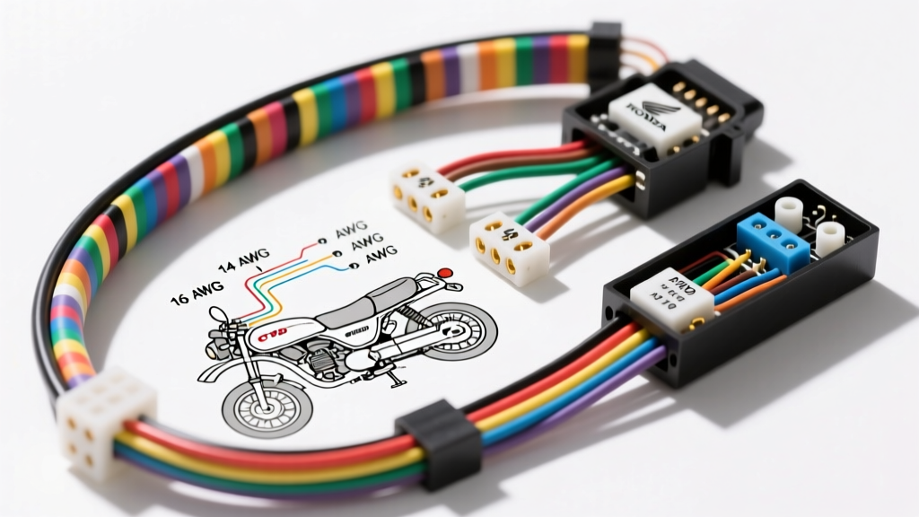
The Challenge: Vintage Honda Colors and Color Vision Deficiency
When consulting a standard ct90 wiring diagram for colorblind people, the immediate hurdle is Honda's vintage 1960s and 1970s color palette. For mechanics with Deuteranopia or Protanopia (red-green color vision deficiency), distinguishing between Honda's signature Red (DC power) and Green (chassis ground) wires is nearly impossible. Both hues often degrade into a muddy, indistinguishable brown or yellowish-gray, especially when exposed to decades of engine heat, oil vapor, and UV radiation.
Futhermore, the CT90 Trail 90 relies on subtle tracer stripes—such as Black/White for the ignition kill circuit versus Black/Yellow for the ignition coil feed. When a wiring diagram for colorblind people is needed, relying solely on visual color identification is a recipe for crossed circuits, blown rectifiers, and dead batteries. This advanced technical deep dive bypasses color reliance entirely, teaching you how to map the Honda CT90 harness using wire gauge (AWG), connector topography, pin matrices, and multimeter diagnostics.
Rethinking the CT90 Harness: Topology Over Color
To successfully navigate the CT90 electrical system without relying on color, we must shift our diagnostic paradigm from visual identification to physical and electrical verification. The Honda CT90 (spanning the 6-volt K0-K5 models from 1966-1976 and the 12-volt K6-K8 models from 1977-1979) utilizes a highly logical physical routing system.
1. Wire Gauge (AWG) and Physical Thickness Mapping
According to SAE J1128 standards for low-tension primary cables, wire thickness correlates directly with current load. By using a digital caliper or an AWG wire stripper gauge, you can identify a circuit's function regardless of its faded insulation color.
- 14 AWG (approx. 1.63mm diameter): Used exclusively for the main battery positive feed (OEM Red) and the main chassis ground (OEM Green). These are the thickest wires in the harness, typically terminating in heavy-duty ring terminals at the battery and frame.
- 16 AWG (approx. 1.29mm diameter): Reserved for high-draw accessories and main harness trunks, such as the headlight power feed and the main alternator stator outputs.
- 18 AWG (approx. 1.02mm diameter): The standard gauge for 90% of the CT90 harness, including ignition circuits, turn signals, tail lights, and switch grounds.
- 20-22 AWG: Rarely used on the CT90, but occasionally found in internal speedometer illumination or delicate sensor pigtails.
2. Connector Topography and Pin Position Matrices
Honda utilized specific connector types that act as physical keys. The main harness connects to the rear sub-harness via a hard plastic multi-pin block. By memorizing the pinout cavity positions, you can identify wires even if they are completely black with grease.
- Male/Female Bullet Connectors: Honda uses 3.5mm insulated bullet connectors for most lighting and ignition circuits. The main power and ground use larger, un-insulated or heavy vinyl-covered ring terminals.
- The 4-Pin Main Block: Located near the battery tray, this block connects the main chassis harness to the rear fender harness. Cavity positions are fixed: Pin 1 is consistently the tail light feed, while Pin 2 is the rear brake light switch feed.
- Stator Connector: The alternator wires emerge from the left crankcase cover and plug into the main harness via individual bullet connectors housed in a rubber boot. The physical position of the wire exiting the rubber grommet dictates its function, regardless of color.
CT90 Circuit Identification Matrix (Color-Blind Friendly)
The following table provides a definitive reference for identifying CT90 circuits using physical and electrical properties rather than visual color codes. This data is cross-referenced with factory service documentation archived by the CT90-CT110 Registry.
| Circuit Function | OEM Color (Reference) | AWG Size | Connector / Pin Location | Multimeter Diagnostic Test |
|---|---|---|---|---|
| Main Battery Power | Red | 14 AWG | Ring Terminal / Main Fuse | 12V/6V DC constant (Ignition OFF) |
| Chassis Ground | Green | 14 AWG | Ring Terminal to Frame | < 0.5 Ohms to Battery Negative |
| Headlight AC Feed | Yellow | 18 AWG | Handlebar Switch Block | AC Voltage spikes with engine RPM |
| Rectifier AC Input | White | 18 AWG | Rubber Boot near Stator | AC Voltage present when engine running |
| Ignition Kill Switch | Black/White | 18 AWG | Spade Connector at Switch | Continuity to Ground when switch is OFF |
| Ignition Coil Feed | Black/Yellow | 18 AWG | Spade at Primary Coil | 12V/6V DC at Ignition ON (Points Open) |
| Tail Light Feed | Brown/White | 18 AWG | Main Block Pin 1 | 12V/6V DC when Headlight Switch is ON |
| Left Turn Signal | Orange | 18 AWG | Handlebar Switch Block | 12V DC pulsing (with flasher relay active) |
Stator and Rectifier Deep Dive: The 6V vs 12V Transition
One of the most critical aspects of the CT90 wiring diagram for colorblind mechanics is understanding the alternator output. The CT90 stator generates Alternating Current (AC). On early 6-volt models, the AC is routed directly to the headlight switch (Yellow wire) and to a simple selenium rectifier (White wire). On later 12-volt models, a solid-state silicon rectifier and voltage regulator are introduced.
If you cannot distinguish the Yellow (AC to Headlight) from the White (AC to Rectifier), you risk sending unregulated AC voltage directly into the DC battery circuit, which will instantly boil the battery acid and destroy the bulb filaments. How to verify without color:
- Disconnect the main harness connector.
- Start the engine (you can bypass the harness by jumping the coil directly to a 6V/12V source for testing).
- Set your multimeter to AC Volts.
- Probe the stator output wires. The wire that shows a massive, unregulated AC voltage swing (up to 20V+ at high RPM) that correlates directly with the headlight switch routing is your Yellow wire.
- The wire that routes to the small, finned metal box (the rectifier) bolted to the frame is your White wire. The rectifier will only allow DC to pass through its output terminal.
Multimeter Diagnostics: The Colorblind Mechanic's Best Tool
For a colorblind mechanic, a high-quality digital multimeter (DMM) replaces the eyes. When tracing a suspected ground wire (OEM Green) versus a switched power wire (OEM Black), use the following protocol:
Continuity and Resistance Testing Protocols
- Isolate the Circuit: Disconnect the battery negative terminal to prevent back-feeding through the bulb filaments, which can cause false continuity readings.
- Set DMM to Ohms (Ω): Select the lowest resistance range.
- Establish a Known Ground: Clip your black DMM probe to a clean, bare metal spot on the engine case or frame.
- Probe the Suspect Wire: Touch the red DMM probe to the terminal of the wire in question.
- Interpret the Data: If the DMM reads less than 1.0 Ohm, you have found a Honda Green (Ground) wire. If the DMM reads "OL" (Open Loop) or infinite resistance, the wire is a power feed, switch leg, or ignition circuit.
Common CT90 Failure Points Unrelated to Color Confusion
While misidentifying wires due to color blindness can cause catastrophic shorts, many CT90 electrical gremlins are mechanical in nature. Be vigilant for the following:
- Ignition Points Plate Grounding: The points plate must ground through its mounting screws to the engine case. If corrosion builds up under the plate, the Black/Yellow wire will never complete the circuit to ground, resulting in zero spark, regardless of harness integrity.
- Handlebar Switch Grounding: The horn button and high/low beam switches on the CT90 handlebars rely on the handlebars themselves for grounding. If the handlebars are painted, powder-coated, or heavily rusted, the switches will fail. Always run a dedicated 18 AWG ground pigtail from the switch housing to the main harness.
- Fuse Holder Corrosion: The inline glass fuse holder on the main Red power wire is notorious for internal corrosion. Voltage drop across this corroded connection will mimic a dead battery or a failing stator.
Conclusion and Authoritative References
Navigating a ct90 wiring diagram for colorblind people requires a fundamental shift from visual pattern recognition to tactile, topological, and electrical verification. By memorizing AWG gauge applications, understanding connector cavity layouts, and relying heavily on multimeter continuity and voltage-drop testing, you can diagnose, repair, and restore a vintage Honda Trail 90 with absolute precision, regardless of your color vision capabilities.
For further reading and to verify specific year-over-year harness variations, consult the following authoritative resources:
- The CT90-CT110 Registry - The premier archive for vintage Honda Trail wiring schematics and factory service manual PDFs.
- SAE J1128: Low Tension Primary Cable - The definitive standard for automotive wire gauge specifications, insulation thickness, and current-carrying capacity.
- Honda Powersports Official Documentation - For OEM part numbers regarding replacement multi-pin connector blocks and insulated bullet terminals.