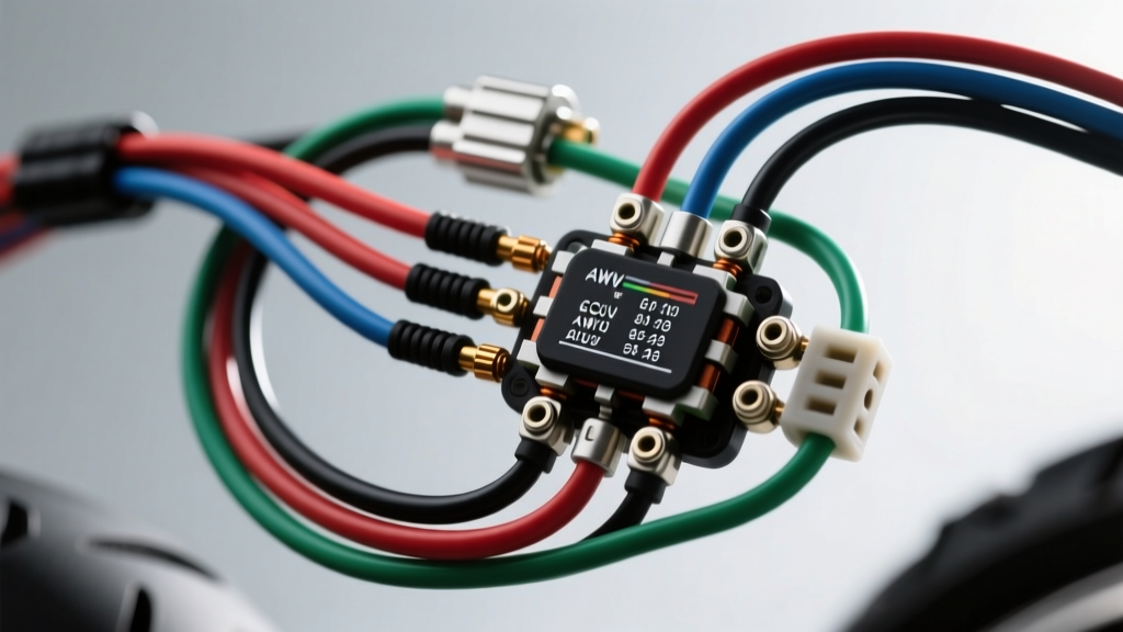
Introduction to Modern Sportbike Electrical Architecture
Decoding a modern motorcycle wiring diagram requires a fundamental shift from viewing the electrical system as a simple battery-and-bulb loop to understanding it as a high-speed, multiplexed data network combined with high-current power generation. Modern sportbikes and ADV motorcycles utilize sophisticated Engine Control Units (ECUs), ride-by-wire throttle bodies, and lean-angle-sensitive ABS modules. When analyzing a complex motorcycle wiring diagram, technicians must trace not only 12V power and ground paths but also 5V reference signals, high-side/low-side injector drivers, and Controller Area Network (CAN) bus physical layers. This advanced technical deep dive dissects the critical nodes of a modern motorcycle electrical system: the three-phase stator generation circuit, the ECU sensor integration matrix, and the environmental sealing standards of OEM connectors.
Stator to Rectifier/Regulator (R/R) Circuit Analysis
The heart of the motorcycle charging system is the permanent magnet alternator (stator). Unlike automotive alternators which use an electromagnet rotor to regulate output, a motorcycle stator generates maximum AC voltage proportional to engine RPM. The raw three-phase AC must be converted to DC and clipped to a safe 14.2V–14.8V DC threshold by the Rectifier/Regulator (R/R). On a factory motorcycle wiring diagram, the stator output is almost universally represented by three Yellow wires routing from the engine case to the R/R.
Three-Phase AC Output & Wire Sizing
A common failure point in sportbikes (notably early 2000s to 2010s Japanese inline-fours) is the melting of the stator-to-R/R connector. The OEM diagram often specifies 12 AWG (approx. 3.3 mm²) wire for the stator phases. However, under high electrical load (heated grips, auxiliary lights, high-beam HID), the stator can output upwards of 35 to 45 Amps of continuous AC current. The resulting thermal load on standard PVC-insulated 12 AWG wire, combined with the high resistance of degraded OEM spade terminals, causes catastrophic connector failure. Advanced rewiring protocols dictate bypassing the OEM plastic connector entirely, soldering the joints with high-silver content rosin-core solder, and sealing them with adhesive-lined marine heat shrink. Alternatively, upgrading the phase wires to 10 AWG (5.2 mm²) high-temperature silicone wire significantly reduces resistance and thermal buildup.
| Parameter | OEM Standard (Typical) | Heavy-Duty Upgrade | Technical Justification |
|---|---|---|---|
| Wire Gauge (AWG) | 12 AWG (3.3 mm²) | 10 AWG (5.2 mm²) | Reduces voltage drop and I²R heating at 40A+ loads. |
| Insulation Material | PVC (Cross-linked) | Silicone / PTFE | Withstands engine case ambient temps exceeding 120°C without melting. |
| Max Continuous Current | 41 Amps | 55 Amps | Provides a 30% safety margin for aftermarket electrical accessories. |
| Connector Type | Standard 6.3mm Spade | Solder / Adhesive Heat Shrink | Eliminates micro-arcing and oxidation at the R/R junction. |
ECU Pinout Mapping and Sensor Integration
Modern motorcycle ECUs (such as the Bosch ME17.9 or Continental M3C) utilize high-density 48-pin or 60-pin waterproof connectors. Reading the ECU section of a motorcycle wiring diagram requires distinguishing between power feeds, sensor inputs, and actuator outputs. The ECU operates on a strict 5V reference logic for analog sensors, utilizing a ratiometric measurement system to determine throttle position, manifold pressure, and ambient temperatures.
TPS, IAT, and MAP Sensor Signal Tracing
On the wiring diagram, analog sensors typically share a common 5V reference line and a dedicated analog sensor ground. It is a critical diagnostic rule that the sensor ground is not the same as the chassis power ground. The ECU provides an isolated, regulated 5V ground return path to prevent voltage fluctuations from the fuel pump or cooling fan from skewing the sensor readings. For instance, a Throttle Position Sensor (TPS) will have three wires: a 5V Reference (often Red/White), a Sensor Ground (often Black/White), and the Signal Return (often Green/Blue). If a technician incorrectly grounds the TPS signal wire to the engine block instead of routing it back to the ECU's dedicated sensor ground pin, the ECU will read erratic voltage spikes every time the fuel injector fires, resulting in severe hesitation and lean-running conditions.
| Pin Number | Function | Wire Color Code | Wire Gauge (AWG) | Signal Type / Voltage |
|---|---|---|---|---|
| 1 | CAN-High | Green/White | 20 AWG (0.5 mm²) | Differential Data (Dominant ~3.5V) |
| 2 | CAN-Low | Green/Yellow | 20 AWG (0.5 mm²) | Differential Data (Dominant ~1.5V) |
| 14 | 5V Sensor Reference | Red/White | 20 AWG (0.5 mm²) | Regulated 5.0V DC ± 0.05V |
| 15 | Analog Sensor Ground | Black/White | 20 AWG (0.5 mm²) | Isolated 0V Return |
| 32 | Injector 1 (Low-Side Driver) | White/Blue | 18 AWG (0.75 mm²) | Switched Ground (Peak 70V+ flyback) |
| 45 | Main Relay Control | Yellow/Red | 18 AWG (0.75 mm²) | Low-Side Driver (12V Switched) |
Connector Types and Environmental Sealing
The physical integrity of the wiring harness is just as critical as the schematic logic. Motorcycle wiring diagrams will often denote specific connector families using standardized symbols or part number callouts. Understanding the mechanical and environmental limits of these connectors is vital for harness repair and aftermarket integration.
Deutsch DTM vs. Sumitomo TS Connectors
While automotive applications heavily rely on standard Metri-Pack or Weather-Pack connectors, the motorcycle industry favors high-vibration, ultra-compact sealed connectors. The Sumitomo TS (Thin Sealed) 090 series is the OEM standard for Japanese sportbikes. These connectors utilize a 0.90mm blade width and require a specific silicone rubber plug (dummy seal) for any unused cavities to maintain IP67 waterproofing. Crimping Sumitomo terminals requires a specialized F-crimp die; using a standard open-barrel automotive crimp tool will deform the terminal, preventing it from locking into the plastic housing's internal lance.
Conversely, aftermarket accessories (like auxiliary DENALI or Baja Designs lighting) and premium European motorcycles (BMW, KTM) frequently utilize Deutsch DTM or DT series connectors. Deutsch connectors use a solid cylindrical pin and socket design with a silicone rear wire seal grommet. They are rated for severe vibration and continuous moisture exposure. When repairing a Deutsch connector, the wire seal must be pushed completely over the insulation crimp barrel, and the terminal must be inserted until an audible 'click' confirms the internal retention clip has engaged.
Advanced Troubleshooting: Voltage Drop & Parasitic Draw
When the wiring diagram indicates a circuit is complete, but the component fails to operate, advanced diagnostics require moving beyond simple continuity testing. Continuity tests use less than 10 milliamps of current and cannot detect high-resistance faults under load.
Voltage Drop Testing the Main Ground Bus
Modern motorcycles route the ECU, fuel pump, and ABS module grounds to a centralized ground bus on the frame or engine block. To test this, set a digital multimeter to DC Volts. Place the positive probe on the battery negative terminal and the negative probe on the ECU ground pin (back-probed). With the ignition ON and the fuel pump priming, the voltage drop must not exceed 0.1V DC. A reading of 0.3V or higher indicates severe corrosion at the frame ground eyelet, which will artificially lower the 5V reference signals and cause the ECU to miscalculate fuel injection duration.
Parasitic Draw and the Immobilizer Circuit
When tracing parasitic battery drains using the wiring diagram to isolate fuses, technicians must account for the immobilizer and ECU 'sleep' cycles. Modern motorcycles feature multiple CAN-bus modules (Instrument Cluster, ABS, ECU) that remain awake for up to 15 minutes after the ignition is turned off to perform data logging and system checks. A true parasitic draw test requires waiting 20 minutes for the CAN bus to enter sleep mode. Acceptable parasitic draw for a modern motorcycle with an active RFID immobilizer antenna is typically between 1.5 mA and 3.0 mA. Draws exceeding 5.0 mA will discharge a small YTZ7S or YTX7L-BS AGM battery within 7 to 10 days of inactivity.
Authoritative References
- SAE International J1128: Low Voltage Primary Cable Standard - Defines the thermal, mechanical, and electrical requirements for automotive and motorcycle primary wiring insulation and AWG sizing.
- Bosch Motorsport Technical Documentation - Provides comprehensive pinout architectures, CAN-bus physical layer specifications, and sensor integration matrices for modern ME17.9 and M3C ECUs.
- Haynes Motorcycle Service Manuals - The industry benchmark for OEM wiring schematics, connector cavity maps, and factory diagnostic flowcharts for Japanese and European motorcycles.