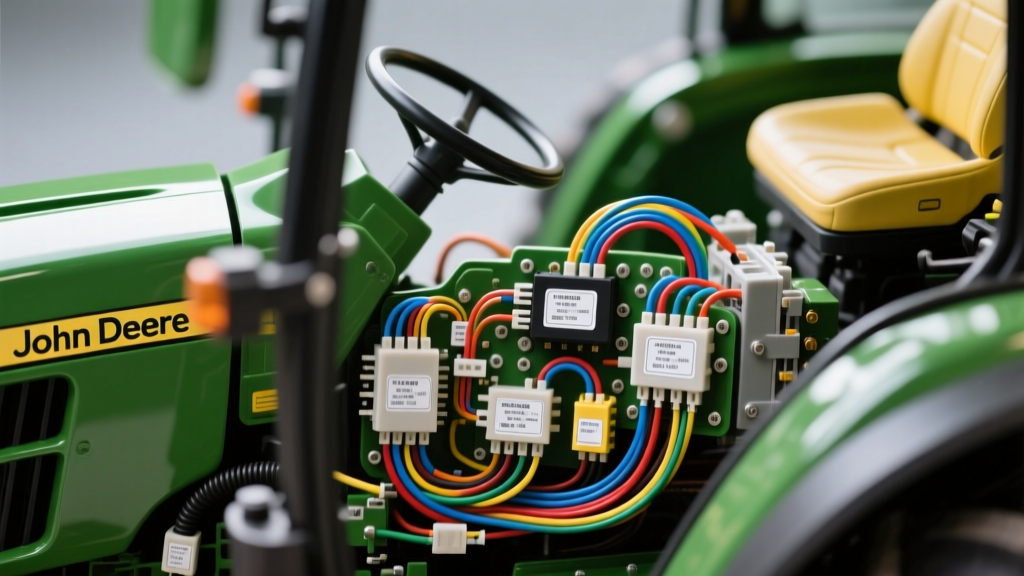
The Critical Role of OEM Schematics in Agricultural Modifications
Upgrading heavy agricultural equipment requires far more than just bolting on aftermarket parts and hoping for the best. Modern tractors are essentially rolling networks of computers, sensors, and multiplexed data lines. When planning a major electrical overhaul or precision ag integration, securing a reliable schematic john deere wiring diagram download is the foundational step that separates a professional-grade integration from a fire-hazard nightmare. Whether you are retrofitting a classic 8000 Series tractor with a modern auto-steer system or upgrading the factory halogen work lights to high-draw LED bars, guessing wire colors or pinouts will inevitably lead to blown fuses, damaged Body Controllers (BC), or corrupted CAN bus networks.
For this guide, we are focusing on the legendary John Deere 8400 and the broader 8000 Series platform. These machines are prime candidates for modernization, but their electrical systems require a methodical approach. By utilizing the OEM schematic, we can identify the exact splice points, wire gauges, and connector types required to execute these modifications without triggering a cascade of dashboard fault codes.
Decoding the John Deere Electrical Architecture
Before cutting into a single wire, it is vital to understand that modern John Deere tractors utilize a hybrid electrical architecture. While high-current components like the starter and alternator rely on traditional heavy-gauge hardwiring, the vast majority of the tractor’s accessories, sensors, and displays communicate over a Controller Area Network (CAN bus) governed by the SAE J1939 Standard.
The Body Controller (BC) and Engine Control Unit (ECU) act as the central nervous system. If you tap into a lighting circuit without consulting your schematic john deere wiring diagram download, you risk backfeeding voltage into a sensitive 5V reference circuit. Furthermore, John Deere utilizes Pulse Width Modulation (PWM) for lighting and sensor monitoring, meaning the BC actively measures current draw. If your modification alters the expected resistance or amperage, the BC will shut down the circuit to protect itself.
Project 1: Integrating Aftermarket Precision Ag GPS (J1939 CAN Bus)
Adding an aftermarket Trimble or John Deere StarFire GPS receiver requires tapping into the tractor’s data bus to read engine RPM, ground speed, and steering angle. The safest and most reliable access point is the Agricultural Management Solutions (AMS) port or the standard 9-pin diagnostic connector. Never use "T-taps" or "scotch locks" on CAN bus wires; the high-frequency data signals are highly susceptible to impedance changes and voltage drop caused by poor connections.
AMS and Diagnostic Port Pinout Specifications
Most 8000 Series tractors feature a 6-pin Deutsch DT connector for AMS devices, or a 9-pin Deutsch HD10 for diagnostics. Referencing your wiring diagram, locate the J1939 backbone. Below is the standard pinout configuration for integrating your GPS receiver:
| Pin / Cavity | Function | Wire Color (OEM) | Wire Gauge | Splice Method |
|---|---|---|---|---|
| Pin A | CAN High (J1939) | Yellow | 18 AWG | MIL-Spec Solder Sleeve |
| Pin B | CAN Low (J1939) | Green | 18 AWG | MIL-Spec Solder Sleeve |
| Pin C | Battery + (Unswitched) | Red | 12 AWG | Heat Shrink Butt Splice |
| Pin D | Chassis Ground | Black | 12 AWG | Ring Terminal to Block |
| Pin E | Drain / Shield | Bare / Shield | N/A | Capped (Do not ground) |
Expert Tip: The CAN bus requires a 120-ohm terminating resistor at each physical end of the network. When splicing into the AMS port, ensure your aftermarket GPS harness does not contain an internal terminating resistor, or you will drop the network resistance to 40 ohms, causing widespread communication failures across the ECU and transmission controllers.
Project 2: High-Draw LED Work Light Harness Upgrade
Factory halogen work lights on the 8400 typically draw 55W each. Upgrading to modern LED light bars drastically improves nighttime visibility, but it introduces two major electrical hurdles. First, LEDs draw significantly less current, which can cause the Body Controller to register a "bulb out" fault. Second, if you are adding auxiliary roof-mounted LED bars (e.g., four 50W bars), the factory 14 AWG roof harness cannot safely handle the 200W+ inrush current, risking melted insulation.
Bypassing the Body Controller PWM Limits
To properly execute this modification, use your schematic john deere wiring diagram download to locate the factory cab roof lighting relay trigger wire. Instead of running the LED bars directly through the factory PWM circuit, we will use the factory signal wire to trigger a heavy-duty, weather-sealed ISO relay mounted in the engine bay.
| Circuit Segment | Required AWG | Wire Type | Protection |
|---|---|---|---|
| Factory Switch to Relay Coil (Pin 85/86) | 18 AWG | TXL (Cross-linked) | 5A Inline Fuse |
| Battery to Relay Power (Pin 30) | 10 AWG | SGT (Battery Cable) | 30A MAXI Fuse at Battery |
| Relay Load to LED Bars (Pin 87) | 12 AWG | TXL (Cross-linked) | 20A Circuit Breaker |
By isolating the high-current draw to a dedicated 10 AWG harness, you protect the delicate internal traces of the John Deere Body Controller. The factory switch merely acts as a low-current signal trigger, completely bypassing the PWM current-monitoring limitations while retaining full cab control.
Troubleshooting Common Modification Fault Codes
Even with a perfect schematic john deere wiring diagram download, environmental factors and vibration can cause post-installation issues. Here is how to diagnose the most common modification-related fault codes on the JD GreenStar or CommandCenter display:
- BC 00004 (Lighting Circuit Open/Short): If this appears after an LED swap, the Body Controller has detected an abnormal voltage drop. Verify your ISO relay trigger circuit. If you wired the LEDs directly to the factory harness, you must install a PWM-compatible load resistor (typically 10-ohm, 50W) in parallel with the LED to simulate the halogen current draw.
- ECU 000190 (Engine Speed Signal Erratic): Often caused by electromagnetic interference (EMI) from poorly shielded aftermarket LED drivers or GPS antennas. Ensure all CAN bus splices are wrapped in copper braided shielding and that the drain wire is properly terminated. Check the TE Connectivity Deutsch DT Connector Specs to ensure your crimp tool is applying the correct pressure to the solid core pins, preventing micro-arcing.
- CAN Bus Communication Loss (U-Codes): Disconnect the battery and use a digital multimeter (DMM) to measure resistance across Pin A (Yellow) and Pin B (Green) on the diagnostic port. A healthy J1939 network will read exactly 60 ohms. If you read 120 ohms, a terminating resistor has failed or a splice has broken the backbone. If you read 40 ohms, an aftermarket device is improperly injecting a third terminating resistor into the network.
Essential Tools and Safety Protocols
Executing these modifications requires specialized tools. Standard electrical tape and wire nuts have no place in high-vibration, high-moisture agricultural environments. You must utilize a John Deere Precision Ag Technology approved approach to wiring. Invest in a high-quality ratcheting Deutsch pin crimper, a variable-temperature heat gun for dual-wall adhesive heat shrink, and MIL-Spec Raychem SolderSleeves for all data bus splices. Always disconnect the negative battery terminal and wait 15 minutes for the Body Controller capacitors to discharge before cutting into any OEM harness. By combining the right tools with the exact data from your OEM schematics, your upgraded 8000 Series tractor will perform flawlessly in the harshest conditions for years to come.