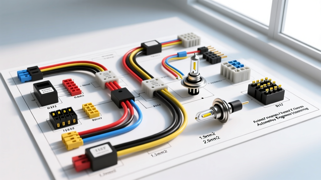
Technical Reference: Headlight High Beam Low Beam Wiring Diagram Configurations
Understanding the headlight high beam low beam wiring diagram is critical for diagnosing illumination faults, upgrading to LED or HID systems, and repairing melted OEM pigtails. Modern vehicles utilize either dual-filament halogen capsules or separate single-filament bulbs controlled by Body Control Modules (BCMs) or Totally Integrated Power Modules (TIPMs). This technical specification reference details the exact pinouts, wire color codes, AWG requirements, and circuit architectures for the most common dual-beam headlight systems found in global automotive applications.
Dual-Filament Bulb Pinouts and Connector Specifications
Dual-filament bulbs house both the low beam and high beam filaments within a single glass envelope. The wiring harness must supply a common ground and two separate switched power feeds. Below are the industry-standard pin configurations for the most prevalent connectors.
H4 / 9003 / HB2 (3-Pin Connector)
The H4 (and its DOT-equivalent 9003/HB2) is the most ubiquitous dual-filament connector globally. It features three flat spade terminals arranged in a triangular pattern. While the physical connector is universal, the pinout can vary between Japanese and European manufacturers.
- Standard Pinout (Asian/Domestic): Pin 1 (Ground), Pin 2 (Low Beam +), Pin 3 (High Beam +).
- Alternate Pinout (European/VW/Audi): Pin 1 (Low Beam +), Pin 2 (Ground), Pin 3 (High Beam +).
Expert Note: Always verify the ground circuit with a multimeter before installing an LED conversion kit. Applying 12V to a ground pin due to an assumed pinout will instantly destroy the LED driver.
9007 vs. H13 vs. 9004 (3-Pin & 4-Pin Connectors)
These cylindrical connectors with plastic locking rings are heavily used in North American domestic vehicles (Ford, GM, Chrysler). While they look similar, their internal pin mappings and physical keying differ significantly.
- 9007 (Ford/GM): Pin 1 (Ground), Pin 2 (Low Beam +), Pin 3 (High Beam +).
- H13 (Ford/Chrysler): Pin 1 (Ground), Pin 2 (Low Beam +), Pin 3 (High Beam +). Electrically identical to 9007, but the locking ring and rubber seal diameter differ to prevent cross-insertion.
- 9004 (Older Toyota/Dodge): Pin 1 (Ground), Pin 2 (High Beam +), Pin 3 (Low Beam +). Note the reversal of pins 2 and 3 compared to the 9007.
According to SAE J1292 Automotive Electrical Systems standards, wire color coding for these circuits generally follows a black ground convention, though power feed colors vary wildly by OEM.
Wire Gauge (AWG) and Current Draw Specifications
Selecting the correct wire gauge is paramount to preventing voltage drop and melted connectors. Halogen dual-filament bulbs draw significant current, particularly when the high beam filament (typically 60W-65W) is engaged. The table below outlines the electrical load and required American Wire Gauge (AWG) specifications based on cross-linked polyethylene (TXL/GXL) insulation ratings.
| Circuit Segment | Typical Load (Watts) | Current Draw (@ 13.5V) | Recommended AWG (TXL) | Max Voltage Drop Allowance |
|---|---|---|---|---|
| Single Bulb Pigtail (Low Beam) | 55W | 4.07A | 16 AWG (OEM) / 14 AWG (Upgrade) | < 0.2V |
| Single Bulb Pigtail (High Beam) | 60W | 4.44A | 16 AWG (OEM) / 14 AWG (Upgrade) | < 0.2V |
| Main Harness Feed (Per Side) | 60W (Max Continuous) | 4.44A | 14 AWG | < 0.5V |
| Relay Battery Feed (Both Sides) | 120W (Combined High) | 8.88A + Inrush | 12 AWG | < 0.3V |
| Relay Coil Trigger (BCM Switch) | N/A (Inductive) | < 0.5A | 18 AWG | N/A |
Relay-Based Headlight Circuit Architecture
Many older OEM headlight high beam low beam wiring diagrams route the full headlight current through the steering column multifunction switch. This architecture is highly prone to switch melting and severe voltage drop, resulting in dim halogen output. Upgrading to a relay-based harness isolates the high-current load from the factory switch.
Standard Bosch 5-Pin Relay Integration
When designing or repairing an aftermarket relay harness for dual-beam systems, two standard ISO mini relays are required (one for low, one for high). The pin assignments are as follows:
- Pin 30: Constant 12V+ from Battery (12 AWG, fused at 15A).
- Pin 87: Switched 12V+ Output to Headlight Bulb (14 AWG).
- Pin 86: 12V+ Trigger from OEM Headlight Switch / BCM (18 AWG).
- Pin 85: Chassis Ground (18 AWG).
- Pin 87a: Normally Closed (Unused in standard headlight applications).
For comprehensive relay load and lifecycle specifications, refer to the Littelfuse Automotive Relay Datasheets.
PWM, CANBUS, and Modern BCM Integration
Modern vehicles (post-2010) rarely use simple 12V switched feeds for headlights. Instead, the BCM or TIPM utilizes Pulse Width Modulation (PWM) to monitor circuit integrity and detect bulb outages. The HELLA Technical Lighting Portal notes that OEM modules send a high-frequency square wave (often varying between 5V and 12V) to measure the resistance of the incandescent filament.
When referencing a modern headlight high beam low beam wiring diagram for LED upgrades, you must account for this PWM signal. LEDs lack the thermal mass and resistance of a halogen filament, causing the BCM to interpret the circuit as 'open' (bulb out), triggering dashboard errors or hyper-flashing. The wiring solution requires integrating a CANBUS decoder or a high-wattage load resistor in parallel with the low beam circuit to simulate the 55W halogen load.
Diagnostic Decision Tree: Ground Offset and Backfeeding
A common failure mode in dual-filament wiring is 'backfeeding,' where the low beam filament glows dimly when the high beams are engaged. This is rarely a short circuit; it is almost always a high-resistance ground fault.
- Symptom: High beams turn on, but low beams remain dimly lit instead of turning off.
- Cause: The primary ground wire (Pin 1) has corroded or backed out of the connector, creating high resistance.
- Circuit Path: Current flows from the High Beam (+) pin, through the high beam filament, and seeks a ground. It travels backward through the low beam filament, into the low beam (+) wire, and finds a ground path through the BCM or multifunction switch circuitry.
- Fix: Perform a voltage drop test across the ground pin and the battery negative terminal with the high beams engaged. A reading above 0.2V confirms a ground fault. Repair the ground terminal or install a dedicated 14 AWG ground bypass directly to the chassis.