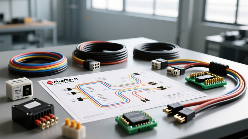
Understanding the FuelTech FT550 Wiring Diagram Basics
Transitioning from a factory engine harness to a standalone engine management system is a major milestone for any gearhead or amateur race car builder. The FuelTech FT550 is one of the most popular standalone ECUs on the market, offering incredible datalogging, boost control, and sequential fuel injection capabilities. However, staring at a blank canvas of unterminated wires can be deeply intimidating. This beginner-friendly guide breaks down the core concepts of the fueltech ft550 wiring diagram, translating complex schematic jargon into actionable, step-by-step automotive wiring advice.
Whether you are wiring a turbocharged LS swap, a dedicated drag car, or a street-driven import, understanding how to properly route power, ground your sensors, and configure your outputs is the difference between an engine that fires right up and one that suffers from mysterious electrical gremlins. We will focus on the universal principles of the FT550 harness, emphasizing wire gauge selection, pinout configurations, and critical shielding techniques.
The Foundation: Power and Ground Distribution
The most common cause of standalone ECU failure and erratic sensor readings is inadequate power and grounding. The FuelTech FT550 requires a massive, clean, and stable 12V supply to operate its internal processors and drive high-current outputs. According to SAE J1128 standards for automotive electrical wire, you must select a wire gauge that can handle the maximum current draw without suffering from voltage drop.
For the FT550, the main power and ground circuits should be wired using 10 AWG TXL (Cross-Linked Polyethylene) wire. TXL wire is preferred over standard PVC primary wire because it features thinner insulation, higher heat resistance, and superior flexibility, making it ideal for tight engine bay routing.
- Main Power (Pins A1 & A2): Must be fed from a switched 12V+ source via the main EFI relay. Use 10 AWG Red TXL wire.
- Power Ground (Pins A27 & A28): Must be routed directly to the vehicle's battery negative terminal or a dedicated, clean chassis ground point tied directly to the battery. Use 10 AWG Black TXL wire. Never rely solely on the engine block for the ECU's primary ground.
- Ignition Switch Trigger (Pin A3): This tells the ECU to wake up. Use 18 AWG wire connected to a clean 12V ignition-on source.
The Main EFI Relay Circuit
Beginners often make the critical mistake of wiring the ECU directly to the ignition switch. The ignition switch cannot handle the 20+ amps required by the ECU, injectors, and fuel pumps simultaneously; this will melt the switch and cause severe voltage drop. You must use a Bosch-style 5-pin or 4-pin heavy-duty relay.
- Pin 30 (Input): Constant 12V from the battery via a mega fuse (40A-60A). Use 10 AWG wire.
- Pin 87 (Output): Switched 12V output. This feeds ECU Pins A1/A2, the injector power bus, and the ignition coil power bus. Use 10 AWG wire.
- Pin 85 (Ground): Grounded to the chassis. Use 18 AWG wire.
- Pin 86 (Trigger): Triggered by the ignition switch (12V+ when key is in the 'ON' position). Use 18 AWG wire.
FuelTech FT550 Connector A Pinout Reference
The FT550 utilizes a multi-connector harness setup, typically divided into Connectors A, B, C, and D. Connector A is the 'brain stem' of the ECU, housing the main power, grounds, and critical engine speed/position sensors. Below is a simplified reference table for the essential pins on Connector A (34-pin Deutsch or AMP connector depending on your specific harness generation).
| Pin Number | Function | Recommended Wire Color | Wire Gauge (AWG) |
|---|---|---|---|
| A1 | Main 12V Power (Switched) | Red | 10 AWG |
| A2 | Main 12V Power (Switched) | Red | 10 AWG |
| A15 | Crank Sensor Signal (+) | Shielded Twisted Pair | 22 AWG |
| A16 | Crank Sensor Signal (-) | Shielded Twisted Pair | 22 AWG |
| A27 | Power Ground | Black | 10 AWG |
| A28 | Power Ground | Black | 10 AWG |
| A33 | Sensor Ground (Signal) | Brown | 20 AWG |
Note: Always verify your specific harness pinout against the official FuelTech USA Support documentation, as universal harnesses can be customized by the manufacturer or previous owners.
Wiring Injectors and Ignition Coils (Connector B)
Connector B is dedicated to the high-current outputs: fuel injectors and ignition coils. The FuelTech FT550 features built-in peak-and-hold circuitry, meaning it can natively drive low-impedance (high-flow) injectors without the need for external ballast resistors or injector drivers.
Injector Wiring Best Practices
For the injector power feed, run a dedicated 12V+ bus using 12 AWG or 10 AWG wire that branches off to each injector using 18 AWG pigtails. The ground side of the injector is triggered by the ECU. Use 20 AWG wire for the ECU ground trigger signals. Keep the injector power and ground wires as close to each other as possible to minimize the electromagnetic loop area, which reduces radiated noise.
Ignition Coil Wiring
When wiring smart coils (like LS-style truck coils or IGN1A coils), the ECU only provides the logic ground trigger. The coils require their own dedicated 12V+ and power ground. Do not ground ignition coils to the ECU sensor ground; the high-current flyback voltage generated when the coil fires will instantly destroy the ECU's internal processor. Always ground ignition coils directly to the cylinder head or engine block using a dedicated ground strap.
Sensor Inputs: Shielding and Signal Grounds
The FT550 reads a variety of sensors, including Throttle Position (TPS), Manifold Absolute Pressure (MAP), Coolant Temperature (CLT), and Intake Air Temperature (IAT). The most critical sensors to wire correctly are the Crank and Cam position sensors, especially if you are using Variable Reluctance (VR) magnetic sensors.
VR sensors generate a raw AC voltage signal that is highly susceptible to Electromagnetic Interference (EMI) from ignition coils and alternators. You must use 22 AWG Shielded Twisted Pair (STP) cable for VR sensors. The metallic shield inside the cable acts as a Faraday cage, absorbing EMI.
- The Golden Rule of Shielding: The shield drain wire must be connected to the ECU's dedicated Sensor Ground pin (Pin A33) only. Leave the shield completely disconnected and insulated at the sensor end. Grounding the shield at both ends creates a 'ground loop,' turning your shield into an antenna that will cause misfires at high RPM.
- Sensor Grounds: All 5V reference sensors (MAP, TPS) and resistive sensors (CLT, IAT) must use the ECU's dedicated Sensor Ground pins. Never ground these sensors to the engine block, as the voltage differential between the block and the ECU will skew your readings, causing erratic fueling.
CAN Bus Configuration (Connector D)
The FT550 features a robust CAN (Controller Area Network) bus system, allowing it to communicate with digital dashes, external boost controllers, and telemetry modules. CAN bus operates on a differential signal using CAN High and CAN Low wires.
Use 22 AWG twisted pair wire for the CAN bus. The entire network must be properly terminated using 120-ohm resistors at the two physical extremes of the bus. If your digital dash has a built-in terminator and the FT550 has a built-in terminator, ensure both are enabled, and do not add extra resistors in the middle of the harness, as this will drop the resistance below the required 60-ohm parallel threshold and cause communication dropouts.
Common Beginner Wiring Mistakes and Troubleshooting
Even with a perfect wiring diagram, small execution errors can prevent the engine from starting. Use this decision tree to diagnose common standalone ECU wiring faults:
- Symptom: Engine cranks, but FT550 shows 0 RPM on the datalog.
- Cause 1: VR sensor air gap is too wide. Fix: Adjust crank sensor to sit 0.020 to 0.040 inches from the reluctor wheel teeth.
- Cause 2: Shield grounded at both ends. Fix: Cut the shield drain wire at the sensor connector; ensure it is only grounded at ECU Pin A33.
- Cause 3: Swapped Crank + and Crank - wires. Fix: Swap the signal wires at the ECU connector.
- Symptom: Injectors are clicking, but engine floods and won't fire.
- Cause: Ignition coil power ground is missing, or ECU trigger is wired to the wrong pin. Fix: Verify 12V+ at the coil power pin with a multimeter during cranking. Verify coil grounds are bolted to the cylinder head, not the ECU.
- Symptom: Erratic TPS or MAP readings that jump randomly.
- Cause: 5V reference wire is too thin, or sensor is grounded to the block. Fix: Ensure sensor ground wire is routed back to Connector A's sensor ground pins. Use 20 AWG or thicker for 5V reference lines to prevent voltage drop.
- Symptom: ECU loses connection or reboots when the fuel pump kicks on.
- Cause: Fuel pump is sharing the same ground or 12V trigger circuit as the ECU, causing a massive voltage spike/drop. Fix: Wire the fuel pump relay trigger to a separate output on the FT550 (Connector C) and ensure the fuel pump has its own dedicated 10 AWG ground to the chassis.
Final Thoughts on Harness Construction
Building a harness for a FuelTech FT550 is a test of patience and precision. Always use high-quality crimping tools—such as those from Molex or Deutsch—to terminate your pins. A poorly crimped pin will eventually vibrate loose or corrode, leading to a catastrophic engine failure on the track. Wrap your finished harness in split loom tubing or high-temperature fiberglass sleeving, and secure it with Tesa tape to prevent chafing against the chassis. By respecting the fundamentals of wire gauge, proper grounding, and signal shielding, your FT550 will provide years of reliable, high-performance engine management.