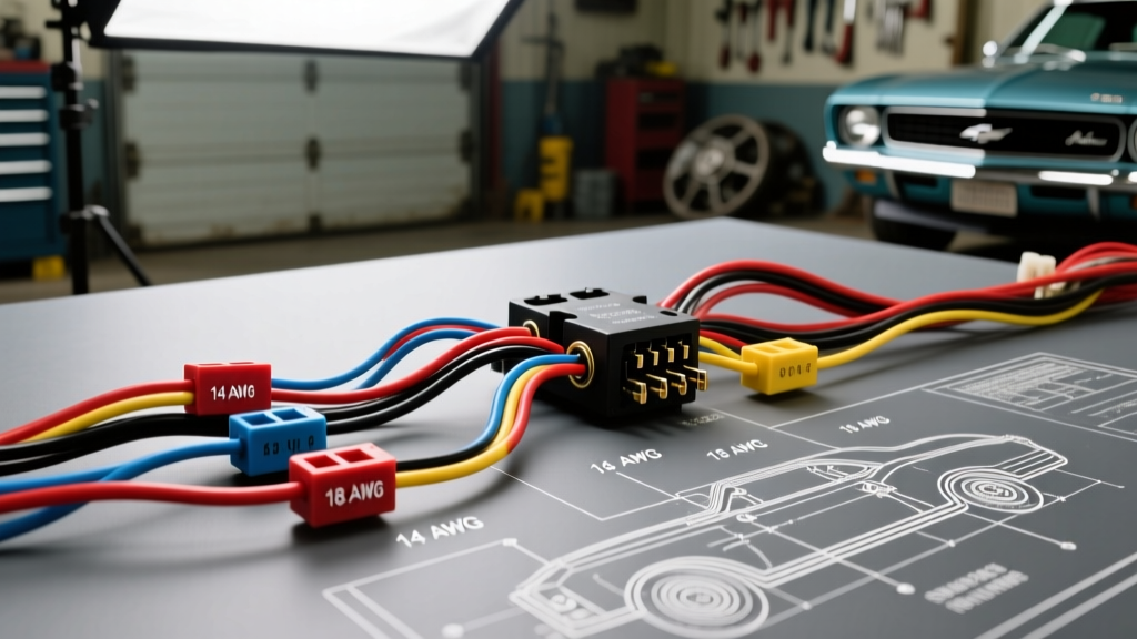
Decoding the Classic Car Wiring Diagram: The 1969 GM F-Body Blueprint
Restoring a vintage vehicle requires more than just bodywork and mechanical overhauls; it demands a thorough understanding of the vehicle's electrical nervous system. When enthusiasts search for a classic car wiring diagram, the 1969 Chevrolet Camaro serves as the gold standard for understanding late-60s unibody electrical architecture. Unlike modern vehicles that rely on complex CAN-bus networks and multiplexed modules, the 1969 Camaro utilizes a straightforward, hard-wired, unbussed topology. Every circuit is a dedicated physical path from the power source to the load, controlled by mechanical switches and relays.
However, simplicity does not mean immunity to failure. Decades of heat cycling, vibration, and DIY modifications often leave original harnesses brittle and unreliable. This complete wiring diagram walkthrough will dissect the primary circuits of the 1969 Camaro, detailing OEM wire color codes, AWG (American Wire Gauge) specifications, and critical connector pinouts. Whether you are troubleshooting a dim headlight issue or rewiring the chassis from scratch, mastering these schematics is essential for a safe and functional restoration.
The Main Bulkhead Connector: Firewall Pass-Through
The most critical junction in any classic GM wiring harness is the bulkhead connector. This multi-pin block routes power and signals from the engine bay (forward lamp harness) through the firewall into the passenger cabin (dash and body harness). In the 1969 Camaro, this connector is a frequent source of voltage drop due to galvanic corrosion and loose terminal tension.
When reading the classic car wiring diagram for the firewall pass-through, you must pay close attention to the heavy-gauge feeds. The main battery feed and alternator output must handle high amperage without melting the plastic housing. Below is the specification chart for the primary cavities in the 1969 Camaro main bulkhead connector.
| Cavity ID | Wire Color | AWG Size | Circuit Function |
|---|---|---|---|
| A | Red | 12 AWG | Main Battery Feed to Dash/Headlight Switch |
| B | Black | 10 AWG | Alternator Main Output to Battery/Horn Relay |
| C | Brown | 14 AWG | Tail Light & License Plate Lamp Feed |
| D | Dark Green | 14 AWG | Right Hand Stop/Turn Signal Feed |
| E | Yellow | 14 AWG | Left Hand Stop/Turn Signal Feed |
| F | Light Blue | 18 AWG | High Beam Indicator Lamp Feed |
Pro-Tip: When restoring this connector, never use dielectric grease on the crimp barrels themselves, as it can impede the crimping process. Apply a high-quality copper anti-seize or electrical contact cleaner to the male and female terminals to ensure optimal conductivity and prevent future oxidation.
Headlight and Front Lighting Circuit Walkthrough
The forward lighting circuit on the 1969 Camaro is a masterclass in heavy-load mechanical switching. Power originates at the horn relay bus bar (fed directly by the 10 AWG Black alternator wire and the 12 AWG Red battery feed). From the bus bar, a 12 AWG Red wire travels to the headlight switch on the dashboard.
Floor-Mounted Dimmer Switch Specifications
Unlike modern column-mounted stalks, the 1969 Camaro utilizes a floor-mounted dimmer switch to toggle between high and low beams. The headlight switch sends a 12 AWG Red feed to the dimmer switch. The dimmer switch then splits the circuit:
- High Beam Output: Light Green (14 AWG) - Routes to the dual-filament sealed beams and taps off to the Light Blue (18 AWG) high-beam indicator on the dash.
- Low Beam Output: Tan (14 AWG) - Routes directly to the low-beam filaments of the sealed headlights.
Because the entire headlight load (roughly 35-40 amps combined) passes through the dash switch and the floor dimmer, voltage drop is a common failure mode. Many restorers use the classic car wiring diagram to install a heavy-duty headlight relay kit. By using the original Tan and Light Green wires merely as low-amp trigger signals for 40-amp Bosch-style relays, you deliver full battery voltage directly from the horn relay bus bar to the headlights, drastically improving night-time visibility.
Ignition Switch and the Famous Ballast Resistor Wire
The ignition system of a classic points-style V8 requires careful attention to voltage regulation. The 1969 Camaro ignition switch is a 4-post mechanical unit mounted on the steering column, featuring terminals for BAT (Battery), ACC (Accessory), IGN (Ignition), and START.
When tracing the IGN terminal on the wiring diagram, you will find a 12 AWG Pink wire. However, this wire transitions into a highly specialized resistance wire (often identifiable by a cloth braid or a distinct 'resistance' marking) before reaching the positive terminal of the ignition coil. This wire has an internal resistance of approximately 1.8 ohms.
Why is this critical? Standard breaker-point distributors require roughly 9 volts to operate efficiently and prevent the points from arcing and burning prematurely. During engine cranking, the START terminal sends a full 12V bypass via a Yellow (16 AWG) wire directly to the coil to ensure a hot spark while the starter draws heavy amperage. Once the key returns to the IGN position, the bypass drops out, and the coil is fed through the 1.8-ohm resistance wire, dropping the voltage to a safe 9V. If you replace this specialized wire with standard 12 AWG copper during a rewiring project, you will rapidly destroy the ignition points and condenser.
Charging System: External Voltage Regulator Pinout
Before the advent of the internally regulated 10-SI alternators in the mid-1970s, the 1969 Camaro utilized a Delco-Remy externally regulated alternator. The classic car wiring diagram for this system routes four distinct wires from the alternator and ignition harness to the voltage regulator mounted on the driver-side radiator support.
Understanding these four terminals is crucial for troubleshooting a 'no-charge' condition:
- BAT (Terminal 1): Red (12 AWG). Connects directly to the horn relay bus bar. Provides the main charging output path.
- IGN (Terminal 2): Pink with a White tracer (16 AWG). Receives switched 12V from the ignition switch. This 'wakes up' the regulator when the engine is running.
- F (Terminal 3 - Field): Brown (18 AWG). Connects to the alternator's field terminal. The regulator pulses this circuit to control the magnetic field strength inside the alternator, thereby controlling voltage output.
- 2 (Terminal 4 - Sense): Blue (18 AWG). Connects to the main battery feed at the horn relay. This allows the regulator to 'sense' the actual voltage at the battery and adjust the field circuit accordingly.
If your classic car is overcharging or undercharging, the first step is to check the Blue sense wire. If this 18 AWG wire is broken or has high resistance due to corrosion, the regulator will falsely read low voltage and command the alternator to output maximum voltage, potentially boiling the battery.
Troubleshooting Vintage Harnesses and Grounding Strategies
When using a classic car wiring diagram to chase electrical gremlins, technicians must remember that the vehicle's steel unibody serves as the primary ground return path. The original 1969 schematics show ground points indicated by small star-washers and sheet metal screws. Over time, rust, paint, and undercoating act as insulators, creating massive voltage drops.
According to SAE J1128 Primary Cable Standards, proper grounding requires clean, bare metal contact. When restoring the chassis, always dedicate heavy braided copper ground straps (minimum 8 AWG) from the engine block to the firewall, and from the engine to the front subframe. Do not rely solely on the engine mounting bolts for grounding, as rubber isolators and corrosion will interrupt the return path for high-amp loads like the starter and electric cooling fans.
Furthermore, when replacing damaged sections of a classic harness, avoid using standard PVC-insulated wire found in hardware stores. Modern automotive restorations should utilize TXL or GXL (Cross-Linked Polyethylene) wire. GXL wire features a much thinner insulation wall, allowing for easier routing through tight classic car bulkheads, while offering superior resistance to the high under-hood temperatures that melt vintage PVC insulation.
Upgrading to Modern Alternators
Many restorers choose to upgrade the fragile external regulator system to a modern 12-SI or 3-wire internally regulated alternator. As detailed in the MAD Electrical Alternator Tech guides, a 3-wire setup is vastly superior to a '1-wire' conversion for classic cars. A 3-wire setup utilizes the original Blue sense wire to monitor battery voltage accurately and the original Brown wire (repurposed as an exciter wire via a dash indicator bulb) to turn the alternator on at low RPMs. This ensures your 1969 Camaro charges reliably even at idle, a common failing point of cheap 1-wire conversions.
For comprehensive harness routing and terminal crimping specifications, referencing Painless Performance Wiring Manuals provides excellent visual aids for achieving factory-correct loom wrapping and connector seating. Mastering the classic car wiring diagram is not just about making the lights turn on; it is about preserving the integrity, safety, and reliability of automotive history.