The Challenge of Industrial Power in Mobile Platforms
The integration of high-cap auxiliary power systems into heavy-duty commercial chassis—such as the Freightliner M2 106, Ford F-550, or custom motorhome platforms—requires a meticulous approach to electrical safety. When upfitters build mobile command centers, large luxury RVs, or mobile welding rigs, they frequently need to step down industrial 480V shore power to usable 120/240V AC for interior appliances and HVAC systems. This is where a 15 kVA or 25 kVA step-down transformer becomes essential.
However, a major hazard arises when technicians blindly follow a standard industrial single phase 480 to 120 240 transformer wiring diagram pdf without adapting it for a mobile, dual-grounding environment. Industrial schematics assume a fixed, stationary grounding grid. A vehicle chassis is a dynamic, moving ground plane subject to vibration, moisture, and Electromagnetic Interference (EMI). Applying stationary wiring logic to a mobile platform is a leading cause of catastrophic electrical fires, fried CAN bus networks, and lethal shock hazards.
Decoding the Schematic: Primary vs. Secondary Terminals
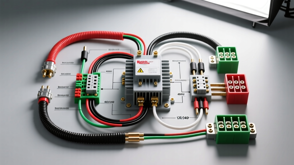
When reviewing your single phase 480 to 120 240 transformer wiring diagram pdf, you will typically see a dual-voltage primary and a four-wire secondary. For a 480V input to 120/240V split-phase output, the internal coil taps must be configured correctly before the transformer is ever mounted to the vehicle's subframe.
- Primary (High Voltage): Terminals H1 and H2. For 480V single-phase operation, the internal copper straps must be set to the series configuration (as opposed to parallel for 240V). Connect the 480V shore lines to H1 and H2.
- Secondary (Low Voltage): Terminals X1, X2, X3, and X4. To achieve 120/240V split-phase (standard for RV and residential-style appliances), X2 and X3 must be bonded together to form the Neutral. X1 provides 120V Leg A, and X4 provides 120V Leg B. The voltage across X1 and X4 will be 240V.
Table 1: Mobile Upfit Terminal & Wire Color Mapping
| Terminal | Function | AWG Size (15kVA) | Wire Color (NEC/Mobile) | Connector Type |
|---|---|---|---|---|
| H1 | 480V Primary Line 1 | 8 AWG | Brown | Panduit LCA8-8 Lug |
| H2 | 480V Primary Line 2 | 8 AWG | Orange | Panduit LCA8-8 Lug |
| X1 | 120V Secondary Leg A | 4 AWG | Black | Polaris Multi-Tap |
| X2/X3 | 120/240V Neutral | 4 AWG | White | Polaris Multi-Tap |
| X4 | 120V Secondary Leg B | 4 AWG | Red | Polaris Multi-Tap |
| EGC | Equipment Ground | 6 AWG | Green/Yellow | Mechanical Lug |
Critical Safety Warning: The Floating Neutral & Chassis Bonding Mistake
The most severe mistake upfitters make when interpreting a single phase 480 to 120 240 transformer wiring diagram pdf is improperly bonding the secondary neutral to the vehicle chassis. In a stationary building, the neutral is bonded to the earth ground at the main service panel. In a vehicle, the 12V/24V DC chassis ground is entirely separate from the AC shore power ground.
The Hazard: If you bond the X2/X3 neutral terminal directly to the Freightliner M2's steel frame, any imbalance in the 120V loads will push AC return current through the vehicle's chassis. This creates 'objectionable current' that can electrify the exterior skin of the RV or command center, posing a lethal shock risk to anyone touching the vehicle while standing on wet ground. Furthermore, this AC current will induce severe noise into the vehicle's 12V DC system, potentially destroying the Engine Control Module (ECM) and SAE J1939 CAN bus networks.
The Fix: The secondary neutral (X2/X3) must be treated as a 'floating' or separately derived system unless the vehicle is permanently tied to a shore-power grounding grid via a 4-wire shore inlet. According to NFPA 70 (NEC) Article 551 regarding Recreational Vehicles and Mobile Command Centers, the AC neutral must only be bonded to the AC Equipment Grounding Conductor (EGC) at the main shore power transfer switch or inlet, never at the transformer secondary inside the vehicle.
Vibration-Induced Failures: Connector and Routing Protocols
Industrial transformers are heavy and generate significant magnetic hum and heat. When mounted in the exterior electrical bay of a heavy-duty truck chassis, the transformer is subjected to intense road vibration. Standard automotive spade terminals, ring terminals with open barrels, and wire nuts are strictly prohibited on the secondary 4 AWG and primary 8 AWG lines.
All connections to the transformer lugs must use closed-barrel, nylon-insulated crimp lugs, compressed with a calibrated ratcheting crimper. After crimping, dual-wall adhesive heat shrink must be applied to seal the connection against moisture and road salt ingress. For the secondary multi-tap connections (like bonding X2 and X3), use insulated Polaris multi-tap connectors rather than split bolts, which can loosen over time due to chassis torsion.
EMI Shielding and CAN Bus Clearance
The 480V primary lines carry high inrush currents when the transformer is first energized, generating a massive electromagnetic field. If these Brown and Orange 8 AWG wires are routed parallel to the vehicle's J1939 data lines (typically twisted pair, Yellow/Green), the EMI will induce voltage spikes that corrupt data packets, leading to 'Check Engine' lights, limp-mode activation, and erratic dash cluster behavior. Always route 480V AC lines at least 12 inches away from the vehicle's low-voltage DC harnesses, and cross them only at 90-degree angles.
Step-by-Step Verification & Torque Specifications
Before closing the electrical bay and applying 480V shore power, every termination must be torqued to the manufacturer's specifications. Loose connections on a 15 kVA transformer will arc, generating enough heat to melt the terminal block and ignite surrounding insulation.
Table 2: Transformer Lug Torque Specifications
| Terminal Type | Wire Size | Torque (in-lbs) | Tool Required |
|---|---|---|---|
| Primary Coil Lug (H1/H2) | 8 AWG | 45 in-lbs | Calibrated 1/4" Torque Driver |
| Secondary Coil Lug (X1-X4) | 4 AWG | 65 in-lbs | Calibrated 3/8" Torque Wrench |
| Chassis Ground Stud (EGC) | 6 AWG | 120 in-lbs | Calibrated 3/8" Torque Wrench |
Testing Protocol: Once torqued, use a Megohmmeter (Megger) to test the insulation resistance between the primary windings and the transformer core (ground). Apply 1000V DC for 1 minute; the resistance should read greater than 10 Megohms. Next, verify the secondary voltage with a True-RMS multimeter. With no load applied, you should read exactly 120V from X1 to the X2/X3 Neutral, 120V from X4 to Neutral, and 240V across X1 and X4. If you read 240V to neutral on either leg, your internal coil taps are misconfigured, and applying a load will instantly destroy the vehicle's 120V appliances.
Authoritative References
For further technical depth on heavy-duty vehicle upfitting and high-voltage safety, consult the following resources:
- Freightliner M2 106 Body Builder Manual - Essential for understanding chassis grounding points, BEC (Bulkhead Electrical Center) routing, and EMI clearance zones.
- NFPA 70: National Electrical Code (NEC) Article 551 - The definitive legal standard for RV and mobile command center grounding, neutral bonding, and shore power integration.
- SAE J1292: Automobile Wiring - Provides critical guidelines on wire insulation types, vibration resistance, and routing protocols for mobile environments.
By treating your single phase 480 to 120 240 transformer wiring diagram pdf not as an absolute rulebook, but as a baseline that must be heavily adapted for mobile dynamics, chassis torsion, and dual-grounding environments, you ensure a safe, reliable, and code-compliant auxiliary power system for your heavy-duty vehicle.