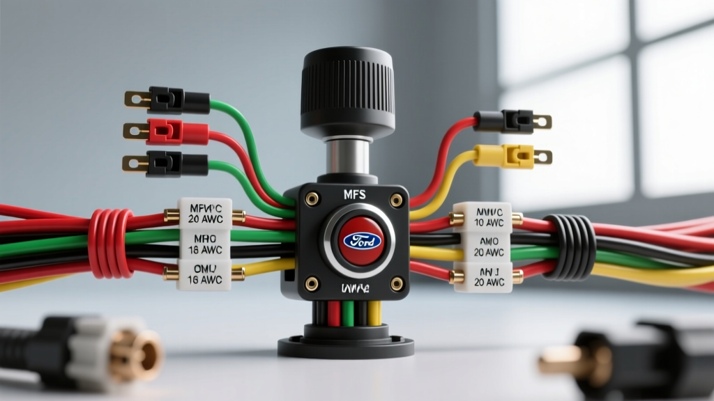
Understanding the Ford Multi-Function Switch (MFS) Architecture
When searching for a turn signal switch Ford steering column wiring diagram, it is critical to understand that Ford transitioned from simple, single-purpose turn signal stalks to the integrated Multi-Function Switch (MFS) in the early 1990s. This guide focuses on the widely documented analog MFS architecture found in the 1992-1996 and 1999-2003 Ford F-Series (F-150/F-250) and Bronco platforms. These steering column switches control the turn signals, hazard flashers, headlight dimmer, and windshield wipers, routing high-current lighting circuits directly through the steering column harness.
Unlike modern vehicles that use low-current multiplexed data signals (CAN/LIN) to trigger body control modules, the classic Ford MFS carries the full amperage load of the exterior lighting. This means the wiring diagram is not just a logic map; it is a high-current power distribution schematic. Understanding the wire gauges, pinout configurations, and mechanical interlocks inside the column is essential for accurate diagnostics and repair.
Comprehensive Pinout and Wire Color Reference Table
The primary connection point for the turn signal and hazard circuits is the 16-pin MFS connector (often designated as C202 or C203 in Ford factory service manuals) located midway down the steering column. Below is the definitive reference chart for the lighting and signal circuits. All wire insulation meets SAE J1128 standards for GXL/TXL cross-linked polyethylene primary cable.
| Pin | OEM Wire Color | AWG Size | Circuit Function |
|---|---|---|---|
| 1 | Light Blue / Black | 14 AWG | Hazard Flasher & Turn Signal Power Feed |
| 2 | Light Green / White | 18 AWG | Left Turn Signal Output (Front & Rear) |
| 3 | White / Light Blue | 18 AWG | Right Turn Signal Output (Front & Rear) |
| 4 | Light Green | 18 AWG | Brake Pedal Switch Input Feed |
| 5 | Brown | 18 AWG | Tail / Running Lights Feed from Headlamp Switch |
| 6 | Black / Pink | 18 AWG | Left Rear Brake/Turn Output to Rear Harness |
| 7 | Light Green / Orange | 18 AWG | Right Rear Brake/Turn Output to Rear Harness |
| 8 | Light Green / Black | 16 AWG | Headlamp Dimmer High-Beam Feed |
Step-by-Step Wiring Diagram Walkthrough
1. Tracing the Hazard and Turn Signal Power Feeds
The lifeblood of the turn signal circuit originates at the under-dash fuse panel. In most F-Series applications, a 15A or 20A fuse protects the hazard/turn circuit. From the fuse, a 14 AWG Light Blue/Black wire routes to the hazard flasher can (typically a 552 thermal relay or an EP34 electronic equivalent). Once the current passes through the flasher relay, it travels up the steering column jacket harness and enters the MFS at Pin 1.
Because the hazard function requires illuminating all four corner bulbs simultaneously, this single Pin 1 feed must handle up to 8.4 amps of continuous draw (assuming four 1157 bulbs drawing 2.1A each on the high-intensity filament). This is why Ford utilized a heavier 14 AWG wire for the feed, while the individual left and right outputs (Pins 2 and 3) only require 18 AWG, as they only carry the load for two bulbs (4.2A max).
2. The Brake Light Interlock Mechanism
The most complex aspect of the turn signal switch Ford steering column wiring diagram is the rear brake light interlock. In Ford vehicles utilizing dual-filament 1157 bulbs at the rear, the turn signal and brake light share the same high-intensity filament. The MFS contains a mechanical cam and copper contactor bridge that manages this priority logic.
When the steering wheel is centered, the 12V feed from the brake pedal switch (Light Green, 18 AWG, Pin 4) passes straight through the MFS and splits to the left and right rear brake outputs. However, when you depress the turn signal lever, the internal cam physically lifts the brake feed contactor away from the corresponding side's output pin. It then bridges the flasher relay feed (Pin 1) to that same output pin. This ensures the rear bulb flashes the turn signal instead of remaining solidly illuminated by the brake switch, while the opposite side continues to receive steady brake light voltage.
3. Steering Column Harness Routing and Ground Points
A common misconception is that the steering column itself serves as the ground path for the MFS. While the column casting is grounded to the chassis via the mounting brackets (torqued to 17 ft-lbs), the MFS lighting circuits do not rely on this. The MFS is a strictly positive-switching device for lighting circuits. The actual ground paths for the exterior bulbs are located at the front radiator core support (G100/G101) and the rear frame rail near the spare tire (G400). If you are experiencing dim turn signals or back-feeding through the dashboard illumination, verify these chassis ground points for corrosion before condemning the column switch.
Real-World Failure Modes: The Melted Connector Pin Epidemic
If you are diagnosing a Ford truck where the turn signals and hazard lights have simultaneously failed, but the fuses and flasher relays test good, you are likely dealing with the infamous melted MFS connector pin. This is a well-documented failure mode across the 1990s and early 2000s Ford truck lineup.
The Physics of the Failure: The hazard flasher circuit routes roughly 8.5 amps through Pin 1 of the 16-pin plastic connector. Over years of exposure to under-dash heat cycles, the copper terminal crimps loosen slightly, increasing electrical resistance. According to Joule's First Law (P = I²R), even a minor increase in resistance at 8.5 amps generates significant localized heat. The heat melts the nylon connector housing, causing the pin to back out, lose contact, and ultimately kill power to the entire turn signal and hazard system.
The Fix: Do not simply replace the plastic connector pigtail; the new one will eventually melt as well. The permanent repair involves cutting the Light Blue/Black 14 AWG feed wire near the column, bypassing the fragile MFS connector pin entirely, and splicing it directly into the harness using a sealed, soldered butt connector or an automotive-grade Deutsch splice. Alternatively, installing an external heavy-duty hazard relay harness removes the high-current load from the steering column switch altogether.
Diagnostic Testing and Multimeter Procedures
Before removing the steering column shrouds or dropping the column (which requires disconnecting the clock spring and airbag on SRS-equipped models), perform a voltage drop test at the base of the column.
- Verify Feed Voltage: Set your digital multimeter (DMM) to DC Volts. Back-probe Pin 1 (Light Blue/Black) at the column base connector. With the hazard switch pulled ON, you should see a pulsing 12V. If you read 0V, the fault is upstream (blown fuse, failed hazard relay, or broken wire in the dash harness).
- Test Output Continuity: Switch the DMM to Ohms (Ω) and disconnect the battery. Back-probe Pin 2 (Left Output) and Pin 4 (Brake Feed). With the turn lever centered, you should read near 0.0Ω (continuity). Pull the lever to the left; the meter should read OL (Open Loop), confirming the mechanical brake interlock is successfully disconnecting the brake feed to allow the flasher signal to pass.
- Check for Voltage Back-feed: If your turn signal indicator on the dash illuminates dimly when you hit the brakes, you have an internal short inside the MFS where the brake feed is arcing over to the turn signal output trace due to carbon tracking or melted internal plastics.
LED Upgrades and Flasher Relay Bypasses
When upgrading exterior lighting to LEDs, the standard thermal 552 flasher relay in the Ford fuse box will not function correctly. Thermal relays rely on the heat generated by the high amperage draw of incandescent bulbs to bend a bimetallic strip. Since LEDs draw less than 0.5A total, the relay will either stay solid or "hyperflash" (flash at double speed). To resolve this without adding dummy load resistors to the rear housings, replace the OEM thermal relay with an EP34 LED-specific electronic flasher. The EP34 uses an internal 555 timer IC to dictate flash rate regardless of circuit amperage, preserving the integrity of the Ford steering column wiring without generating excess heat.
Authoritative References
- SAE International - SAE J1128: Low Tension Primary Cable Standard (Wire insulation and AWG current-carrying specifications).
- AA1Car Automotive Library - Turn Signal & Hazard Flasher Diagnostics (Thermal vs. Electronic relay operational theory).
- Ford Motor Company - Motorcraft Service Information (OEM EVTM Wiring Diagram Manual references for F-Series platforms).