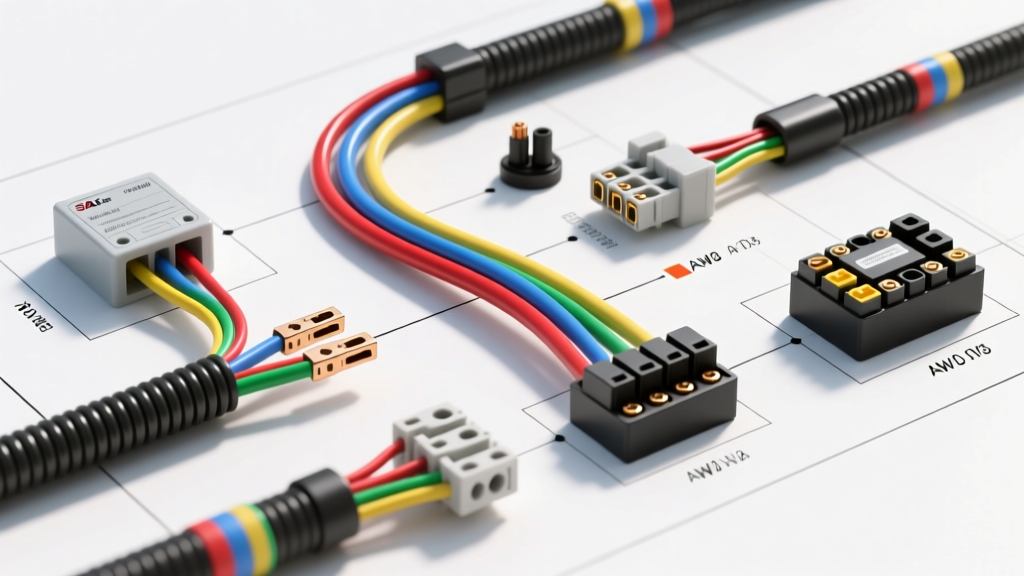
Mastering the Basics: How to Read Free Wiring Diagrams for Cars
When a taillight shorts out, a fuel pump relay fails, or a parasitic draw drains your battery overnight, guessing with a test light is a recipe for melted harnesses and blown Electronic Control Units (ECUs). For beginners and seasoned technicians alike, accessing and understanding free wiring diagrams for cars is the foundational skill of automotive electrical diagnostics. A wiring schematic is not merely a picture of wires; it is a logical map of electron flow, switch states, module pinouts, and ground distribution. This guide breaks down the fundamental architecture of automotive schematics, translating abstract symbols into actionable multimeter tests.
Decoding the Symbols in Automotive Schematics
Every manufacturer—from Ford and GM to Toyota and Honda—uses a standardized set of symbols based on SAE (Society of Automotive Engineers) and DIN/ISO standards. Before tracing a circuit, you must be able to identify the components. Below is a reference table of the most critical symbols you will encounter when reading free wiring diagrams for cars.
| Symbol Name | Visual Representation | Function in the Circuit |
|---|---|---|
| Chassis Ground | Three descending horizontal lines | Connection to the vehicle body or engine block. Usually labeled with a 'G' (e.g., G102). |
| Splice | Black dot on intersecting lines | Indicates wires are physically joined. If no dot is present, wires cross but do not connect. |
| Connector Cavity | Circle with a letter/number | Represents a plug. E.g., 'C104 Pin B' means Connector 104, cavity B. |
| Normally Open (NO) Switch | Gap between two contact points | Switch prevents current flow until mechanically or electronically closed. |
| Resistor / Module | Zig-zag line or boxed rectangle | Represents a load (like a blower motor resistor) or a solid-state control module. |
Understanding SAE Wire Color Codes and Tracer Stripes
One of the most confusing aspects for beginners looking at free car wiring diagrams is the wire color nomenclature. Automotive manufacturers follow SAE J1128 standards for wire coloring to ensure consistency. Wires are rarely a single color; they utilize a base color and a tracer (stripe) color. On a diagram, this is written as BASE/TRACER. For example, BLK/WHT means a Black wire with a White stripe.
- Black (BLK): Universal ground wire. Connects to the chassis or engine block.
- Red (RED): Direct, unfused battery power (hot at all times).
- Pink (PNK): Fused ignition power (hot only in 'Run' and 'Start' positions).
- Yellow (YEL): Starter/Crank circuit power.
- Orange (ORG): Battery/Accessory power (often hot when the ignition is off, like a cigarette lighter).
- Light Green (LT GRN): Typically reserved for turn signals and hazard circuits.
- Dark Blue (DK BLU): Commonly used for high-beam headlights or horn circuits.
Wire Gauge (AWG) and Current Capacity
Wiring diagrams rarely specify the physical thickness of a wire, but understanding American Wire Gauge (AWG) is critical when repairing a harness or adding aftermarket accessories. Using a wire that is too thin for the circuit's amperage will cause voltage drop, overheating, and potentially an electrical fire. Reference this chart when performing harness repairs:
| AWG Size | Max Amperage | Common Automotive Applications |
|---|---|---|
| 18 AWG | 10-14 Amps | ECU sensors, interior LEDs, CAN-bus data lines. |
| 16 AWG | 14-17 Amps | Radio memory, small wiper motors, tail lights. |
| 14 AWG | 18-22 Amps | Power windows, fuel pumps, audio amplifiers. |
| 12 AWG | 25-30 Amps | Cigar lighter sockets, high-power audio, rear defrosters. |
| 10 AWG | 35-40 Amps | A/C blower motors, ABS modules, cooling fans. |
| 8 AWG | 50-60 Amps | Alternator output, heavy-duty winches, EV battery cooling. |
The DIN 72552 Relay Pinout Standard
Relays are the workhorses of automotive electrical systems, allowing a low-current switch (like a steering wheel horn button) to control a high-current load (like dual air horns). Almost all standard 4-pin and 5-pin automotive relays use the DIN 72552 numbering system. When reading a diagram, you will see these numbers inside the relay coil and switch symbols:
- Pin 30 (Common): The main power input from the battery (usually via a fuse).
- Pin 85 (Coil Ground): The ground path for the electromagnetic coil.
- Pin 86 (Coil Power): The switched power that activates the coil.
- Pin 87 (Normally Open - NO): The output to the load. Connects to Pin 30 only when the relay is energized.
- Pin 87a (Normally Closed - NC): Connects to Pin 30 when the relay is at rest. Disconnects when energized (used in 5-pin relays for alarm systems or anti-theft fuel cut-offs).
Expert Tip: Modern vehicles frequently use Ground-Side Switching. Instead of the ignition switch sending power to Pin 86, Pin 86 receives constant battery power, and the Body Control Module (BCM) provides the ground path to Pin 85 to activate the relay. Always check the diagram to see if a module is switching power or switching ground.
Step-by-Step Circuit Tracing: A Real-World Headlight Example
Let's trace a standard low-beam headlight circuit using a generic schematic. Understanding the sequence of electron flow is how you isolate a failure point.
- Power Source: Current leaves the positive battery terminal and travels through a 14 AWG Red wire to the Under-Hood Fuse Box.
- Overcurrent Protection: The circuit passes through a 20A mini-fuse (labeled 'LO BEAM' on the diagram).
- Switching: From the fuse, a Yellow wire carries power to the headlight switch on the dashboard, then to the dimmer/multi-function switch on the steering column.
- Relay Activation: When the driver turns on the low beams, the switch sends power via a Light Green wire to the Headlight Relay (Pin 86). Pin 85 is grounded to the chassis.
- Load Delivery: The relay clicks closed, connecting Pin 30 (Battery Power) to Pin 87. Power flows through a Dark Green 14 AWG wire directly to the low-beam filament inside the headlight bulb.
- Ground Return: The current exits the bulb via a Black 16 AWG wire and travels to Ground Point G102 (located on the left front fender well), completing the circuit back to the battery negative terminal.
If the headlight is dead, you now know exactly where to place your multimeter probes. Check for 12V at the fuse, then at Pin 30 of the relay, then at the bulb connector. If you have 12V at the bulb but it won't light, the failure is a bad ground at G102. Perform a voltage drop test across the ground wire; any reading above 0.1V indicates corrosion or a loose bolt at the ground point.
Locating Splices and Harness Breakouts
Free wiring diagrams for cars often include 'Splice Packs' or 'Harness Breakouts' designated by an 'SP' or 'S' prefix (e.g., SP104 or S201). These are physical locations inside the wire loom where multiple wires are soldered or crimped together to distribute power or data. If you are diagnosing a CAN-bus communication error (like a U0100 code for Lost Communication with ECM), the diagram will show you exactly which splice pack connects the ECM to the ABS module and the instrument cluster. Moisture intrusion into these specific splice packs is a leading cause of ghost electrical issues in older vehicles.
Sourcing Reliable OEM Diagrams
While aftermarket manuals are helpful, they often simplify diagrams to the point of omitting crucial pinout data. For deep diagnostics, rely on authoritative sources. Haynes and Chilton manuals provide excellent baseline schematics for older vehicles. For modern, multiplexed networks, you will need factory-level diagrams that show module pin cavities, CAN-High/CAN-Low twisted pair routing, and termination resistor locations. Understanding these fundamentals transforms free wiring diagrams from confusing webs of lines into powerful diagnostic roadmaps, allowing you to fix automotive electrical issues safely and permanently.