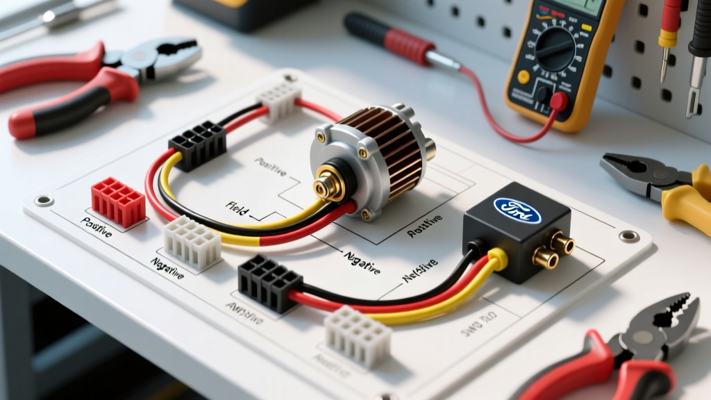
The Anatomy of the 3-Wire Ford Alternator Regulator Plug
When diagnosing or upgrading the charging system on classic and modern Blue Oval trucks, understanding the 3 wire Ford alternator regulator wiring diagram is non-negotiable. While early Fords utilized external voltage regulators with 4-pin harnesses, the widely swapped and highly reliable Ford 3G alternator (and late-model 1G/2G internal regulator variants) relies on a specific 3-wire connector to communicate with the vehicle's electrical system. This 3-pin plug dictates the alternator's output voltage, dash indicator logic, and ignition enablement.
The three circuits are distinctly separated by function: the Stator/Indicator (AS), the Ignition/Enable (I), and the Battery Sense (S). Misinterpreting these circuits during a custom harness build, engine swap, or stereo system upgrade is the leading cause of overcharging, boiled batteries, and fried Powertrain Control Modules (PCMs). Below, we dissect the most catastrophic wiring errors, provide OEM specification tables, and outline critical safety protocols based on automotive electrical engineering standards.
Critical Safety Warnings Before You Splice
Before probing the 3-wire regulator plug or touching the main output stud, adhere to these fundamental safety protocols to prevent electrical fires and component destruction:
- Always Disconnect the Ground First: The main B+ output stud on a Ford alternator is directly tied to the battery positive terminal. Dropping a wrench across this stud and the aluminum alternator housing will cause immediate arc welding, melting tools, and potentially igniting hydrogen gas venting from the battery.
- Verify Wire Insulation Ratings: Never use standard PVC (THHN) wire in an engine bay. You must use automotive-grade cross-linked polyethylene wire (GXL, TXL, or SXL) rated for 125°C to 150°C, as defined by SAE J1128 standards for low-tension primary cable.
- Capacitor Discharge: Modern Ford alternators contain internal suppression capacitors. After disconnecting the battery, wait 60 seconds or use a 10k-ohm bleed resistor across the B+ and ground terminals before cutting into the regulator pigtail.
Top 5 Wiring Mistakes That Destroy Ford Charging Systems
1. Swapping the "I" (Ignition) and "S" (Sense) Circuits
This is the most common and destructive error when reading a 3 wire Ford alternator regulator wiring diagram. The internal voltage regulator uses the "S" (Sense) wire to read the actual voltage at the battery post. The "I" (Ignition) wire simply tells the regulator that the key is in the "Run" position, enabling the field coils.
The Failure Mode: If you swap these two wires, the regulator reads the voltage at the ignition switch rather than the battery. Because the ignition circuit experiences a voltage drop under load (often dropping to 11.5V at the switch while the battery sits at 12.6V), the regulator assumes the battery is dead. It will continuously push maximum amperage, driving system voltage up to 15.5V or higher. This will boil the battery acid, blow headlight bulbs, and eventually fry the vehicle's PCM and sensitive CAN-bus modules.
2. Undersizing the Main B+ Output Cable
The 3-wire plug handles less than 5 amps of control current; the real danger lies in the main B+ output stud. A Ford 3G large-case alternator is rated for 130 amps. Many DIYers incorrectly use 8 AWG wire for the main charge cable because "it looks thick enough."
The Failure Mode: Pushing 130 amps through 8 AWG wire over a 5-foot run creates severe resistance. According to Ohm's Law, this resistance manifests as heat and voltage drop. The wire insulation will melt, potentially shorting against the exhaust manifold or engine block. For a 130A Ford alternator, you must use a minimum of 4 AWG GXL wire for runs under 4 feet, and 1/0 AWG for high-draw audio systems or longer routing paths.
3. Omitting the Inline Mega Fuse or Fusible Link
Every alternator B+ cable must be protected at the source (the battery positive terminal). Relying solely on the internal alternator fuses is a massive safety violation.
The Failure Mode: If the B+ cable chafes against the engine block, the battery will dump hundreds of cold-cranking amps directly into the short circuit, instantly starting an electrical fire. Per SAE J512 automotive fuse standards, a 130A alternator requires a 150A or 175A Mega Fuse installed within 18 inches of the battery positive post. Older 1G setups require a 14 AWG fusible link (which protects a 10 AWG charge wire).
4. Grounding the Stator Wire (Instant Rectifier Death)
Pin 1 on the 3-wire plug is the Stator/Indicator (AS) circuit. This wire taps into the alternator's stator windings before the rectifier bridge, providing an unrectified AC square-wave signal. It is used to illuminate the dash "Battery" warning light and, in some Ford applications, feed the tachometer.
The Failure Mode: Because this wire only carries a few milliamps to illuminate a bulb or trigger a solid-state relay, some installers mistakenly treat it as a ground or accidentally short it to the chassis. Grounding the Stator pin creates a direct short across the stator winding's diode trio. This will instantly overheat and destroy the internal rectifier bridge, killing the alternator's ability to convert AC to DC.
5. Incorrect B+ Terminal Torque and Contact Resistance
The physical connection at the alternator is just as critical as the wiring diagram. The main B+ output stud on a Ford 3G alternator is typically an M8x1.25 thread embedded in the aluminum rear housing.
The Failure Mode: Overtightening the nut will strip the soft aluminum threads or snap the copper stud, requiring a complete alternator teardown. Undertightening allows micro-arcing under high amperage loads, which oxidizes the copper ring terminal and creates a high-resistance bottleneck. The proper torque specification for the M8 B+ nut is 9 to 12 Nm (80 to 106 in-lbs). Always use a dielectric grease on the terminal after torquing to prevent galvanic corrosion.
OEM 3-Wire Pinout & Specification Reference Table
The following table outlines the standard pinout for the Ford 3G 3-wire regulator connector. Note that while wire colors can vary slightly by model year and chassis (e.g., F-150 vs. Mustang), the circuit functions remain identical. Always verify against the specific vehicle's EVTM (Electrical and Vacuum Troubleshooting Manual).
| Pin | Circuit Name | Typical OEM Wire Color | Min AWG | Function & Logic | Failure Symptom if Broken |
|---|---|---|---|---|---|
| 1 | AS (Stator/Indicator) | White/Black or Yellow | 18 AWG | Provides half-wave AC signal for dash warning light and PCM monitoring. | Dash battery light stays on; tachometer drops to zero. |
| 2 | I (Ignition/Enable) | Light Green/Red or White/Yellow | 18 AWG | Switched 12V+ from ignition. Wakes up the internal voltage regulator. | Alternator will not charge; battery drains while driving. |
| 3 | S (Battery Sense) | Yellow/White or Light Green/Yellow | 18 AWG | Reads true voltage at the battery post to regulate field coil duty cycle. | System overcharges (15V+) or undercharges (12.8V) due to voltage drop. |
Troubleshooting Decision Tree: Overcharging and Whine
Use this logical decision tree to diagnose issues related to the 3-wire regulator harness without resorting to throwing parts at the vehicle.
- Symptom: Alternator Whine in Audio System
- Check: Is the main B+ ground wire the same size as the positive wire?
- Fix: Upgrade alternator ground to chassis block using 4 AWG braided strap.
- Check: Is the "S" (Sense) wire spliced into the main B+ cable at the alternator?
- Fix: Reroute the Sense wire directly to the battery positive post to bypass alternator ripple.
- Symptom: Battery Boiling / Voltage Reads 15.2V+ at Idle
- Check: Measure voltage at the "S" pin on the alternator plug with the engine running.
- Fix: If voltage at the "S" pin is lower than voltage at the battery post, repair the open/high-resistance Sense wire. The regulator is overcompensating for a perceived voltage drop.
- Symptom: Dash Battery Light Glows Dimly While Driving
- Check: Measure AC Ripple voltage at the battery with a multimeter set to AC Volts.
- Fix: If AC ripple exceeds 50mV (0.05V), one or more diodes in the rectifier bridge have failed. Replace the alternator or rebuild the rectifier assembly.
Authoritative References
For deeper engineering standards and OEM wiring schematics, consult the following resources:
- SAE International J1128: Low Tension Primary Cable - Standards for automotive wire insulation and temperature ratings.
- SAE International J512: Automotive Fuses - Guidelines for fusible links and high-amperage Mega fuse sizing.
- Ford Service Content & EVTM Archives - Official Electrical and Vacuum Troubleshooting Manuals for model-specific wire color codes and pinouts.