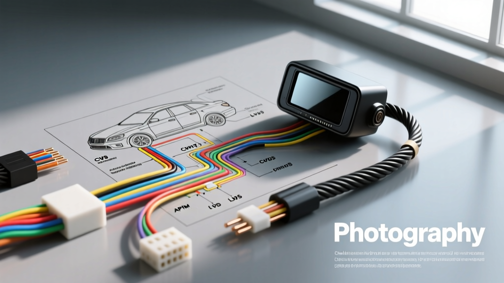
OEM Wiring Diagram for Rear View Camera: CVBS vs. FPD-Link Architectures
When interpreting an OEM wiring diagram for rear view camera systems, modern automotive technicians must look far beyond simple power and ground circuits. The transition from analog composite video to high-speed digital serial links has fundamentally changed how backup cameras integrate with the vehicle's infotainment and Advanced Driver Assistance Systems (ADAS). A factory wiring schematic for a modern rear view camera (RVC) is not just a power delivery map; it is a high-frequency data network blueprint that requires strict adherence to impedance matching, shield grounding, and LIN/CAN bus communication protocols.
This advanced technical deep dive dissects the electrical characteristics, pinout configurations, and diagnostic procedures for modern RVC systems, using the Ford SYNC 3 Accessory Protocol Interface Module (APIM) and FCA Uconnect architectures as primary technical references.
The Electrical Divide: Analog CVBS vs. Digital FPD-Link III
Historically, backup cameras utilized Composite Video Baseband Signal (CVBS). However, as resolution demands increased and cable lengths in large SUVs and trucks exceeded 15 feet, signal degradation and electromagnetic interference (EMI) rendered CVBS obsolete for premium OEM applications. Understanding which protocol your vehicle uses is the first step in reading the wiring diagram correctly.
Analog CVBS Characteristics
In older or base-model vehicles, the wiring diagram will show a single coaxial video line or a shielded twisted pair (STP) carrying the CVBS signal. According to SAE J2922 standards for automotive video interfaces, CVBS operates at a nominal 1.0V peak-to-peak (Vpp) with a 75-ohm characteristic impedance. The signal includes the luminance, chrominance, and synchronization pulses combined into a single baseband waveform. If a wiring diagram specifies a 75-ohm coaxial cable, replacing it with standard unshielded 18 AWG primary wire will result in severe ghosting, rolling horizontal bars (due to 60Hz alternator whine ground loops), and a complete loss of sync pulses.
Digital FPD-Link III / LVDS Characteristics
Modern vehicles utilize Flat Panel Display Link (FPD-Link III) or similar Low-Voltage Differential Signaling (LVDS) protocols. As detailed in Texas Instruments automotive SerDes application notes, FPD-Link III uses a Serializer/Deserializer (SerDes) architecture. The camera module contains a serializer that converts parallel digital pixel data, I2C control signals, and power-over-coax (PoC) telemetry into a high-speed differential serial stream. This requires a 100-ohm differential impedance STP cable. The wiring diagram for these systems will show a differential pair (Video+ and Video-) rather than a single coaxial shield.
Ford SYNC 3 APIM Rear View Camera Pinout & Wiring Diagram
To provide a concrete example of a digital RVC architecture, we will examine the Ford SYNC 3 APIM (Accessory Protocol Interface Module). The APIM acts as the deserializer and graphical processing hub. The camera connects to the APIM via the C2281 connector, utilizing a Shielded Twisted Quad (STQ) or dual-STP harness.
| Pin | Circuit Function | Wire Color (Typical) | AWG | Electrical Specification |
|---|---|---|---|---|
| 1 | RVC Video + (LVDS) | White / Red Stripe | 22 AWG | 100-Ohm Differential Pair (High-Speed Serial) |
| 2 | RVC Video - (LVDS) | White / Black Stripe | 22 AWG | 100-Ohm Differential Pair (High-Speed Serial) |
| 3 | RVC LIN Bus / Control | Yellow / Blue Stripe | 22 AWG | 12V Logic, 19.2 kbps (Local Interconnect Network) |
| 4 | RVC Shield / Drain | Bare / Green | 18 AWG | EMI Shield Ground (Must terminate at APIM chassis) |
Note: The primary 12V power and chassis ground for the camera module itself are typically sourced from the Body Control Module (BCM) or a dedicated rear fuse box, triggered by the Reverse Lamp circuit or a CAN-bus wake-up command, not directly from the APIM C2281 connector.
Wire Gauge, Shielding, and Routing Specifications
When repairing or extending an RVC harness based on the wiring diagram, physical geometry is just as critical as electrical continuity. High-speed LVDS signals are highly susceptible to common-mode noise and crosstalk.
- Impedance Matching: Never solder standard butt connectors onto LVDS pairs. Any splice alters the 100-ohm differential impedance, causing signal reflection and a "Camera Not Available" fault. Use factory-approved crimp sleeves with adhesive-lined heat shrink to maintain the dielectric spacing between the twisted pair.
- Shield Grounding: The drain wire (Pin 4) must be grounded at the APIM side to prevent the shield from acting as a floating antenna. At the camera module side, the shield is often isolated via a capacitor to prevent ground loops between the rear hatch (which has its own ground plane) and the dashboard chassis.
- Separation from High-Current Sources: The RVC harness must be routed at least 150mm (6 inches) away from high-current inductive loads, such as rear window defroster grids, fuel pump power feeds, and ignition coil circuits. Crossing these wires should only be done at strict 90-degree angles.
CAN/LIN Bus Integration and Wake-Up Sequences
A common misconception is that the camera simply turns on when the reverse light receives 12V. In modern architectures, the reverse lamp circuit acts as a hardwired wake-up trigger for the BCM or Rear Camera Module. The BCM then broadcasts a CAN-bus message to the APIM, instructing it to switch the display input. Simultaneously, the APIM sends a LIN-bus command to the camera module to initialize the image sensor and begin streaming LVDS data.
If the LIN bus wire (Pin 3) is severed or shorted to ground, the camera may receive power, but the APIM will never receive the "Handshake Complete" telemetry. The infotainment screen will display a static "Checking Camera" or "Camera Not Available" message, even if the LVDS video lines are perfectly intact.
Advanced Diagnostics: Oscilloscope and Multimeter Tracing
Diagnosing RVC faults requires moving beyond the digital multimeter (DMM). A DMM can only verify DC power and ground; it cannot decode high-frequency video or serial bus anomalies. Referencing the Motorcraft Service Information diagnostic trees, follow these oscilloscope-based verification steps:
1. Verifying the LIN Bus Control Signal
Connect your oscilloscope probe to the LIN bus wire (Pin 3) at the APIM connector. Set the timebase to 5ms/div and voltage to 20V/div. Upon shifting into reverse, you should observe a 12V square-wave logic signal. The dominant state (low) pulls down to near 0V, while the recessive state (high) rests at battery voltage (~12.5V). If the signal is stuck at a flat 12V or 0V, the APIM has detected a hard short/open and has disabled the LIN transceiver to protect the network.
2. Checking LVDS Differential Voltage
While standard oscilloscopes struggle to decode the multi-gigabit FPD-Link stream, you can verify the physical layer's DC bias and common-mode voltage. Using differential probes on Pins 1 and 2, the common-mode voltage should sit between 1.0V and 1.4V. If the DC bias is missing, the serializer inside the camera module has failed to initialize, often due to a corroded Power-over-Coax (PoC) inductor or a failed internal voltage regulator.
Common Failure Modes and Decision Tree
When the wiring diagram confirms continuity but the camera fails, evaluate these real-world failure modes:
- Hatch Flex-Fatigue (Open Circuit): The harness passing through the rubber boot between the roof and the liftgate undergoes thousands of bend cycles. 22 AWG wires will work-harden and snap internally while the insulation remains intact. Perform a loaded voltage drop test across the flex zone while an assistant opens and closes the hatch.
- Water Intrusion and Galvanic Corrosion: Camera modules mounted near the license plate are exposed to road salt and pressure washers. Moisture ingress causes galvanic corrosion on the LVDS pins, increasing contact resistance and destroying the 100-ohm impedance balance. Look for green/white crust on the connector terminals.
- Aftermarket LED Reverse Bulb Interference: If the customer installed aftermarket LED reverse lamps with high-frequency PWM drivers, the EMI can bleed into the unshielded or poorly routed CVBS/LIN lines, causing the APIM to drop the video sync. Reverting to OEM incandescent bulbs or installing a 12V DC relay isolator will confirm this diagnosis.
Mastering the wiring diagram for rear view camera systems requires an understanding of high-speed data networks, RF shielding principles, and serial bus diagnostics. By treating the camera harness as a critical data link rather than a simple accessory wire, technicians can accurately isolate faults and restore OEM-level ADAS functionality.