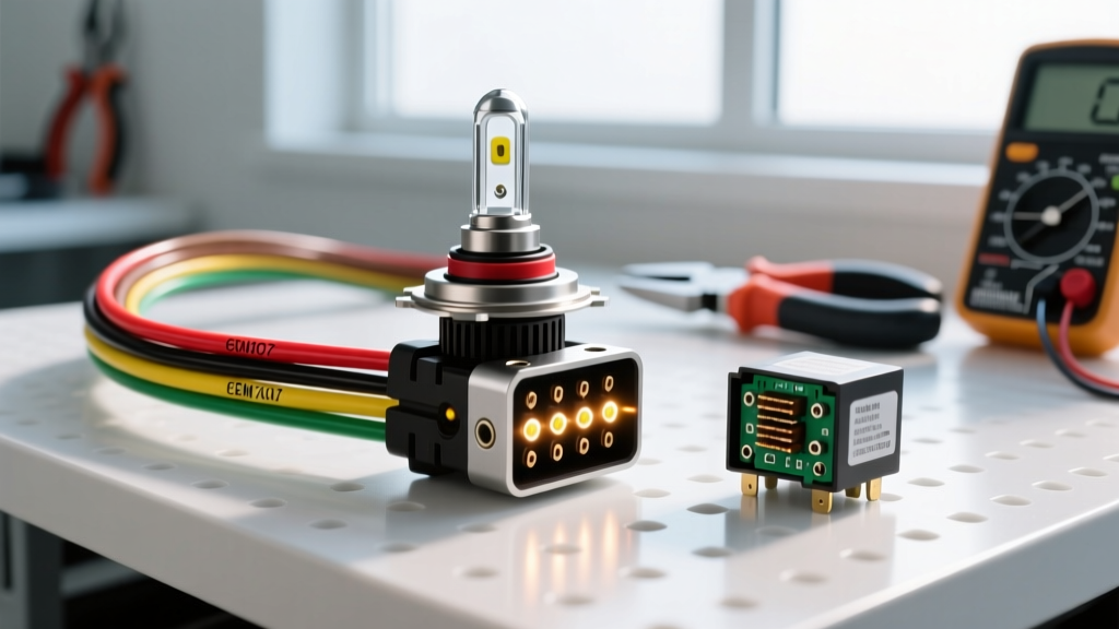
Introduction to the 9007 (HB5) Electrical Architecture
The 9007 headlight wiring diagram represents one of the most common, yet frequently misunderstood, dual-filament halogen circuits in North American automotive history. Officially designated as the HB5 bulb under SAE J1122 specifications, the 9007 bulb features a 55-watt low-beam filament and a 65-watt high-beam filament. Operating at a nominal 12.8V, this translates to a continuous current draw of approximately 4.3 amps on low beam and 5.1 amps on high beam per bulb.
Unlike single-filament setups, the 9007 headlight wiring diagram requires a shared ground circuit and two distinct positive feeds controlled by the vehicle's multifunction switch (MFS) or body control module (BCM). Because both filaments share a common ground path within the bulb base, the integrity of the ground pin is critical. A degraded ground connection doesn't just cause dimming; it can cause current to backfeed through the low-beam filament when the high beams are engaged, resulting in a 'ghosting' effect where both filaments glow weakly. Understanding the exact pinout, wire gauge requirements, and OEM-specific variations is essential for diagnosing electrical faults or upgrading to modern LED arrays.
Standard vs. OEM-Specific 9007 Pinout Configurations
The most notorious trap when working with a 9007 headlight wiring diagram is assuming a universal pinout standard. While the physical 3-way weatherpack connector (often referred to as a PX-291 or HB5 housing) is identical across manufacturers, the internal pin assignments vary drastically between Asian/European standards and domestic American OEMs like Ford and Dodge. Installing an aftermarket LED bulb wired to the 'standard' pinout into a Ford or Dodge will result in reversed high/low beams or a dead short.
| Pin Position (Facing Connector) | Standard / Asian Pinout | Ford / Dodge OEM Pinout | Function |
|---|---|---|---|
| Pin 1 (Left) | Ground (-) | High Beam (+) | Shared Return or High Feed |
| Pin 2 (Center) | Low Beam (+) | Ground (-) | Low Feed or Shared Return |
| Pin 3 (Right) | High Beam (+) | Low Beam (+) | High Feed or Low Feed |
When referencing a factory Haynes automotive electrical manual for a 1999-2003 Ford F-150 or a 2002-2005 Dodge Ram, you will notice the ground circuit is routed through the center pin (Pin 2), whereas standard HB5 applications route ground through Pin 1. Always verify polarity with a digital multimeter (DMM) at the harness pigtail before splicing in new components or LED drivers.
Wire Gauge Specifications and Circuit Load Analysis
Factory wiring for the 9007 circuit typically utilizes 16 AWG (American Wire Gauge) cross-linked polyethylene (XLPE) or PVC-insulated copper wire. At 5.1 amps per high-beam filament, a pair of 9007 headlights draws roughly 10.2 amps total. According to standard automotive ampacity charts, 16 AWG wire is rated for up to 15 amps in engine bay temperatures, making it adequate for stock 65W halogen bulbs.
However, voltage drop becomes a severe issue in older vehicles. A 15-foot run of 16 AWG wire carrying 10 amps will experience a voltage drop of roughly 0.4V. If the factory ground path shares a chassis point with other accessories, or if the battery positive cable is degraded, the voltage reaching the 9007 bulb can drop below 11.5V. Because halogen light output is proportional to voltage to the power of 3.4 ($V^{3.4}$), even a 1-volt drop can reduce headlight luminosity by over 20%. For any 9007 headlight wiring diagram upgrade involving 90W/100W off-road bulbs or high-draw HID ballasts, upgrading the power and ground feeds to 14 AWG or 12 AWG is mandatory to prevent thermal runaway and harness fires.
Diagnosing Common 9007 Wiring and Module Failures
When troubleshooting a 9007 circuit, technicians must look beyond the bulb itself. The following failure modes are endemic to vehicles utilizing the HB5 platform:
- Melted PX-291 Connectors: The 9007 connector is highly susceptible to I²R (current squared times resistance) heating. As the female spade terminals inside the plastic housing oxidize and lose tension, electrical resistance increases. This generates intense localized heat, melting the plastic housing and fusing the connector to the bulb base. The fix requires cutting off the OEM pigtail and soldering/shrink-sealing a new ceramic or high-temp PBT connector.
- Ford Multifunction Switch (MFS) Degradation: In 1990s and early 2000s Ford trucks, the headlight current is routed directly through the turn signal/headlight stalk on the steering column. The internal copper contacts carbon-track and pit over time, leading to high-beam dropouts or melted MFS connectors. Bypassing the MFS with a relay harness is the only permanent repair.
- Dodge TIPM Smart Driver Failures: Later Dodge/Chrysler vehicles route headlight power through the Totally Integrated Power Module (TIPM). The TIPM uses solid-state high-side switches that monitor current draw. If a wire chafes and creates a momentary short, the TIPM's internal logic board may permanently disable that specific circuit to protect the module, requiring a TIPM replacement or an external relay bypass.
Designing a 9007 Relay Harness Upgrade (Step-by-Step)
To eliminate voltage drop and protect factory switches, building a custom 9007 headlight wiring diagram relay harness is the gold standard for automotive electricians. This setup uses the factory headlight wire merely as a low-current trigger signal.
- Power Feed: Run a 10 AWG red wire from the battery positive terminal to an inline 30A MAXI fuse holder, then to Pin 30 of a Bosch-style 30A ISO mini relay.
- Ground Feed: Run a 10 AWG black wire from the relay's Pin 87 directly to the positive terminal of the new 9007 ceramic connector. Ground the new bulb connector's ground pin to a clean, bare-metal chassis point using a ring terminal and star washer.
- Trigger Circuit: Tap into the factory 9007 Low Beam wire using a 16 AWG T-tap or solder joint. Run this to Pin 86 of the relay.
- Relay Ground: Connect Pin 85 of the relay to a solid chassis ground.
When the factory MFS or BCM sends 12V to the low beam wire, it energizes the relay coil (Pins 86 and 85), closing the high-current contact between Pins 30 and 87. This delivers unregulated, full-battery voltage directly to the 9007 bulb, maximizing lumen output and eliminating backfeed issues.
LED Polarity Corrections and TIPM Bypasses
Upgrading to LED 9007 bulbs introduces two major electrical hurdles: polarity sensitivity and CANbus/TIPM hyper-flashing. Unlike halogen filaments, which are resistive and operate on alternating or direct current regardless of polarity, LED driver boards require strict DC polarity. If you plug a standard LED 9007 bulb into a Ford or Dodge harness without adjusting the pins, the LED will not illuminate.
To correct this, use a terminal extraction tool (or a small flathead pick) to depress the locking tangs on the female spade terminals inside the LED's wiring harness. Swap Pin 1 and Pin 3 to match the reversed OEM pinout matrix detailed above. Furthermore, because LEDs draw significantly less current (often under 1.5 amps per bulb) compared to the 4.3A halogen equivalent, Dodge TIPMs and modern BCMs will interpret the low draw as a 'bulb out' condition. This triggers the module to rapidly pulse the circuit (PWM) to test the filament, causing the LEDs to strobe or flicker. Installing a 9007 CANbus decoder or a PWM anti-flicker capacitor module inline between the factory harness and the LED driver is required to stabilize the voltage signal and satisfy the vehicle's diagnostic monitoring routines. For advanced diagnostics on module-level lighting faults, refer to Mopar Tech Authority wiring schematics to identify the exact BCM pinout and bypass the smart-driver circuitry entirely.