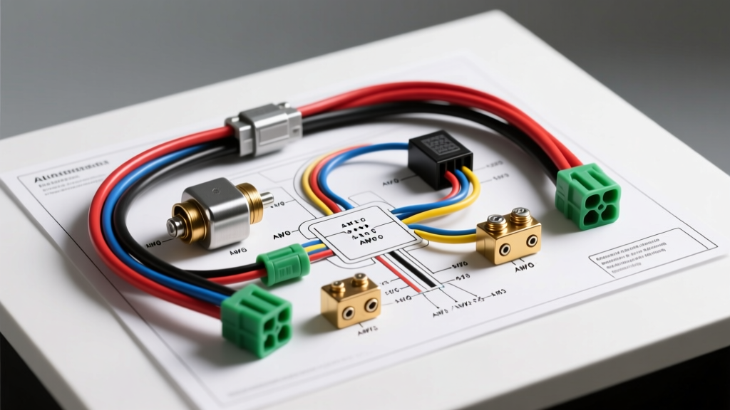
Decoding the Engine Starter Wiring Diagram for Component Selection
When upgrading a classic muscle car, restoring a heavy-duty truck, or troubleshooting a severe no-crank condition, the engine starter wiring diagram is your foundational blueprint. However, a schematic does far more than show you where wires route; it dictates the exact product specifications required for reliable, high-amperage cranking. Selecting the wrong solenoid duty cycle, undersizing your AWG battery cables, or misidentifying relay pinouts will inevitably result in catastrophic voltage drop, solenoid chatter, or melted harness insulation.
This product comparison and selection guide breaks down OEM and aftermarket starter wiring architectures. By understanding the specific demands of your vehicle's platform, you can select the correct high-current cables, control relays, and solenoids to ensure maximum cranking RPM and electrical safety.
Intermittent vs. Continuous Duty: Choosing the Right Solenoid Product
The most common product selection error in high-current automotive circuits is confusing intermittent-duty and continuous-duty solenoids. When reviewing an engine starter wiring diagram, you must match the solenoid's thermal rating to its operational profile.
- Intermittent-Duty Solenoids (Starter Applications): Starter solenoids are designed to handle massive current spikes (300 to 600+ amps) for very short durations, typically under 60 seconds. The internal copper windings are not potted for sustained heat dissipation. If held engaged continuously, an intermittent solenoid will overheat, melt its internal coil insulation, and fail catastrophically.
- Continuous-Duty Solenoids (Winch/Accessory Applications): Products like the Trombetta or Cole Hersee continuous-duty relays are designed to remain engaged for hours without overheating. However, they are generally rated for lower peak amperage (typically 80 to 150 amps). Using a continuous-duty solenoid as a primary starter relay will result in severe voltage drop and insufficient current delivery to the starter motor.
Selection Rule: Always purchase an intermittent-duty, high-amperage solenoid specifically rated for starter motor applications when replacing OEM starter circuit components.
Platform Architecture Comparisons: GM, Ford, and Modern PCM Systems
Different automotive manufacturers utilize vastly different starter control architectures. Your wiring diagram will dictate which relay style and terminal hardware you must select.
GM Starter-Mounted Solenoid (1960s–2000s V8 Platforms)
General Motors utilized a starter-mounted solenoid integrated directly into the motor housing. This design requires running a heavy-gauge main power cable directly to the starter, alongside a lighter-gauge control wire.
- Main Power: 1/0 AWG or 2/0 AWG stranded copper (Red), terminated with a 3/8-inch ring terminal.
- Control Circuit: 12 AWG wire (OEM color: Purple). This wire routes from the ignition switch's 'Start' position directly to the 'S' (Start) terminal on the solenoid.
- Bypass Circuit ('R' Terminal): Older points-style ignition systems utilize the 'R' terminal to send full 12V battery voltage to the ignition coil during cranking, bypassing the ballast resistor. When upgrading to HEI or aftermarket EFI, this wire is eliminated.
Ford Fender-Mounted Solenoid (Pre-1990s V8 Platforms)
Ford separated the heavy-current switching from the starter motor, mounting a heavy-duty relay (solenoid) on the fender well. This keeps the high-amperage cables short and allows the starter to act merely as a motor.
- Main Power: 1/0 AWG cable from the battery to the fender solenoid 'B' terminal, and a second 1/0 AWG jumper from the 'M' terminal to the starter motor.
- Control Circuit: 12 AWG wire (OEM color: Red with Light Green stripe) connected to the 'S' terminal on the fender relay.
- The 'I' Terminal Bypass: Similar to GM, Ford used an 'I' terminal to boost coil voltage during cranking. Crucial Selection Note: If you are swapping a classic Ford to a modern aftermarket gear-reduction starter, you must eliminate the fender solenoid and wire the new starter's integrated solenoid directly, or wire the Ford solenoid as a 'pass-through' to prevent the starter motor from spinning without engaging the Bendix drive.
Modern PCM-Controlled ISO Mini Relays (2000s–Present)
Modern vehicles do not route ignition switch current directly to the starter solenoid. Instead, the PCM (Powertrain Control Module) triggers a standard ISO mini relay (Bosch-style), which then activates the starter. This protects the PCM from high-current feedback and allows for integrated theft-deterrent (immobilizer) logic.
- Pin 30 (Input): 10 AWG or 12 AWG constant 12V+ from the battery or main fuse block.
- Pin 87 (Output): 12 AWG wire routing to the starter solenoid 'S' terminal.
- Pin 86 (Trigger): 18 AWG to 20 AWG wire receiving the low-current 'Crank' signal from the PCM or ignition switch.
- Pin 85 (Ground): 18 AWG wire routing to a clean chassis ground or PCM-controlled ground.
For product selection, always choose an ISO mini relay with an internal suppression resistor or diode (often denoted by a symbol across pins 85 and 86 on the relay casing). This suppresses the inductive voltage spike when the coil de-energizes, protecting sensitive PCM drivers from frying. For deep technical specifications on relay pinouts and load limits, refer to the Littelfuse Automotive Relay Application Guide.
Wire Gauge (AWG) and Terminal Hardware Selection Chart
Undersized wiring is the leading cause of slow cranking speeds and premature starter failure. Use the following specification chart to select the correct AWG wire and terminal hardware based on your engine starter wiring diagram.
| Circuit Application | Recommended AWG | Terminal Type & Size | Hardware / Torque Spec |
|---|---|---|---|
| Battery to Starter Main Feed | 1/0 AWG (or 2/0 for diesel/long runs) | 3/8" or 5/16" Heavy-Duty Ring | 3/8" Stud: 12-15 ft-lbs |
| Battery to Fender Solenoid (Ford) | 1/0 AWG | 5/16" Heavy-Duty Ring | 5/16" Stud: 8-10 ft-lbs |
| Ignition Switch to Control Relay | 12 AWG or 14 AWG | 1/4" Insulated Spade or Ring | Crimp & Heat Shrink Required |
| PCM to Starter Relay (Modern) | 18 AWG or 20 AWG | OEM Metri-Pack / Micro-Pack | Use OEM wedge lock connectors |
Expert Tip: Never use solder-only connections on high-amperage starter cables. The heat generated during cranking can melt solder, causing a complete loss of connection. Always use a closed-barrel, heavy-duty copper lug crimped with a hydraulic or ratcheting hex-crimp tool, followed by adhesive-lined marine-grade heat shrink to prevent corrosion. For comprehensive crimping and marine-grade electrical standards, consult SAE J1171 Electrical Standards.
Product Selection: Upgrading to Gear-Reduction Mini Starters
When swapping from a heavy, direct-drive OEM starter to an aftermarket gear-reduction mini starter (such as those from Powermaster or MSD), your engine starter wiring diagram must be modified. Mini starters draw significantly less peak amperage (often 150-200 amps compared to 400+ amps for OEM) but require specific wiring practices to function correctly.
Most mini starters feature an integrated solenoid with a dedicated trigger terminal. If you are retaining a classic Ford fender-mounted solenoid, you must wire the fender solenoid as a 'pass-through' device. This involves connecting the battery to the fender solenoid, running a heavy cable to the mini starter's main post, and jumping the mini starter's trigger terminal to its own main post. If you wire the trigger wire back to the fender solenoid, the mini starter's internal solenoid will not engage the drive gear, resulting in a 'freewheeling' motor that spins but does not crank the engine.
Diagnostic Troubleshooting: Voltage Drop Testing
If you have selected the correct components and followed the wiring diagram, but the engine still cranks slowly, you must perform a voltage drop test. A voltage drop test identifies hidden resistance in the circuit that a standard multimeter resistance check will miss. According to AA1Car Starting System Diagnostics, testing under load is the only way to verify circuit health.
- Preparation: Set your multimeter to DC Volts. Disable the ignition or fuel system so the engine will crank but not start.
- Positive Side Test: Place the red multimeter probe on the battery positive post (not the clamp) and the black probe on the starter motor main terminal. Crank the engine. A reading above 0.5V indicates excessive resistance in the positive cable, battery terminals, or solenoid contacts.
- Negative Side Test: Place the red probe on the starter motor case (bare metal) and the black probe on the battery negative post. Crank the engine. A reading above 0.2V indicates a poor engine block ground or corroded battery ground cable.
- Control Circuit Test: Place the red probe on the battery positive post and the black probe on the solenoid 'S' trigger terminal. Crank the engine. A drop greater than 1.0V indicates undersized control wiring, a failing ignition switch, or corroded firewall bulkhead connectors.
By strictly adhering to your vehicle's specific engine starter wiring diagram and selecting products that match the thermal and amperage demands of the circuit, you will eliminate cranking failures and ensure long-term electrical reliability.