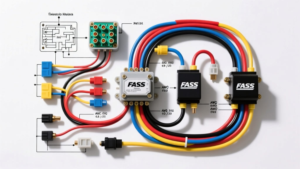
FASS Electrical Architecture Overview
Upgrading to a Fuel Air Separation System (FASS) fundamentally alters the low-pressure fuel delivery architecture of heavy-duty diesel engines. Whether you are installing a Signature Series or the advanced Titanium Series, the electrical demands of the FASS DC lift pump motor are substantial. Under peak load—such as during high-G cornering or maximum fuel demand—the pump motor can draw between 15A and 25A continuously. Because the FASS motor relies on consistent voltage to maintain rotational speed and prevent fuel cavitation, understanding the FASS fuel system wiring diagram is critical for long-term reliability.
Improper wire gauge sizing, excessive chassis grounding resistance, or poor relay terminal crimps will result in severe voltage drop. A voltage drop exceeding 0.5V at the pump connector will cause the motor to slow down, leading to aeration, loss of fuel pressure, and premature brush wear. This technical specification reference details the exact relay pinouts, wire color codes, AWG requirements, and ECM integration protocols required for a factory-grade FASS installation.
Standard FASS Relay Harness Wiring Diagram
The core of the FASS electrical system is the weather-sealed 40A relay harness. This harness isolates the high-amperage draw of the pump motor from the vehicle’s low-amperage ignition switch circuits. FASS utilizes a heavy-duty Bosch-style 5-pin relay enclosed in a molded, water-resistant housing. Below is the exact pinout specification for the main relay block.
Table 1: FASS 40A Relay Block Pinout & Wire Specifications
| Relay Terminal | Function | FASS Wire Color | AWG Size | Connection Point |
|---|---|---|---|---|
| 30 | Main Power Input (Battery +) | Red (w/ Inline MAXI Fuse) | 8 AWG | Direct to Battery Positive or Starter B+ Stud |
| 87 | Switched Power Output to Pump | Red | 8 AWG | Deutsch DT Connector (Pin 1 - Pump +) |
| 85 | Relay Coil Ground | Black | 14 AWG | Chassis Ground or Battery Negative |
| 86 | Relay Coil Trigger (Ignition 12V) | Yellow or White | 14 AWG | Ignition Switched Source (e.g., Fuel Heater, W/T) |
| 87a | Normally Closed (Unused in FASS) | N/A (Capped) | N/A | Sealed with heat shrink to prevent moisture ingress |
Note: Always use an adhesive-lined, dual-wall heat shrink on the 8 AWG ring terminals. Standard vinyl insulation will crack under hood vibrations and allow moisture to corrode the copper strands, increasing resistance over time.
Signature Series: Pressure Switch Safety Circuit
For older FASS Signature Series models, the wiring diagram includes a 1/8" NPT brass pressure switch installed in the fuel discharge block. This switch acts as a critical safety mechanism; it prevents the fuel pump from running if the engine is not turning over (e.g., in the event of an accident where the ignition remains in the "ON" position but the engine stalls).
- Switch Type: Normally Open (NO), closes at 3-5 PSI of oil/fuel pressure.
- Wiring Integration: The Yellow trigger wire (Terminal 86) is routed through the pressure switch before reaching the ignition 12V source.
- Wire Colors: Grey (Switched 12V from Ignition to Switch), Brown (Switched 12V from Switch to Relay Pin 86).
- Failure Mode: If the pressure switch fails open, the relay will never engage, and the pump will not prime. Bypass the switch temporarily with a jumper wire to diagnose a dead pump motor.
Titanium Series: ECM & CAN-Bus Integration Pinouts
The FASS Titanium Series eliminates the mechanical pressure switch in favor of an intelligent ECM/BCM controller. This controller reads engine RPM and manifold boost pressure to dynamically adjust the pump motor speed via Pulse Width Modulation (PWM). This reduces parasitic drag, minimizes fuel heating, and extends motor life. Wiring the Titanium controller requires tapping into the vehicle's OBD-II port or specific ECM harness pins.
Table 2: FASS Titanium ECM Controller Harness (Universal CAN-Bus Tap)
| Controller Pin | Signal Type | Wire Color | Target OBD-II / ECM Pin | Specification |
|---|---|---|---|---|
| 1 | 12V+ Ignition | Red | OBD-II Pin 16 (Battery +) | Fused at 5A (ATM) |
| 2 | Chassis Ground | Black | OBD-II Pin 4 or 5 (Signal Ground) | Clean metal contact, < 0.1Ω |
| 3 | CAN-High | Green | OBD-II Pin 6 (CAN-H) | Splice with MIL-Spec solder sleeves |
| 4 | CAN-Low | Yellow/Green | OBD-II Pin 14 (CAN-L) | Splice with MIL-Spec solder sleeves |
| 5 | Analog Boost (Optional) | Blue | MAP Sensor Signal Wire | 0-5V DC Reference |
| 6 | Tachometer / RPM | White | ECM Tach Output or Crank Sensor | Required for non-CAN vehicles |
Technical Warning: When splicing into the CAN-High and CAN-Low circuits, never use T-taps or scotch-locks. These connectors compromise the twisted-pair impedance (typically 120 ohms) and can cause cascading communication failures across the vehicle's entire network. Always use SAE-compliant solder sleeves with heat-shrink shielding to maintain bus integrity.
Wire Routing, AWG Standards, and Termination
The wiring harness routing from the relay block to the FASS pump motor is where most installation errors occur. The pump is typically mounted on the frame rail, exposed to road debris, water, and extreme thermal cycling from the exhaust system.
- Wire Type: Use only SAE J1128 compliant primary stranded copper wire. Cross-linked polyethylene (XLPE) insulation is preferred over standard PVC due to its higher melting point and resistance to diesel fuel degradation.
- Grounding Protocol: The FASS motor ground (8 AWG Black) must terminate at the vehicle chassis within 18 inches of the pump, or run all the way back to the battery negative terminal. Frame grounding requires sanding down to bare metal, applying a conductive anti-corrosion compound (like Noalox), and torquing the bolt to factory chassis specs (typically 18-25 ft-lbs for M8 hardware).
- Connector Sealing: The pump pigtail utilizes a 2-pin Deutsch DT connector. Ensure the wedge lock is fully seated and the silicone rear seals are compressed. Apply dielectric grease to the pins before mating to prevent galvanic corrosion between the copper wire and the nickel-plated pins.
Diagnostic Decision Tree: Voltage Drop & Motor Cavitation
If your FASS system is exhibiting low fuel pressure, excessive noise (cavitation), or intermittent shutdowns, perform a dynamic voltage drop test while the engine is under load. According to AutoShop 101 Electrical Diagnostics, testing resistance with a multimeter on a disconnected circuit will not reveal high-resistance faults under load.
Voltage Drop Testing Procedure
- Step 1: Set your digital multimeter (DMM) to DC Volts.
- Step 2: Place the red probe on the Battery Positive terminal and the black probe on Relay Pin 30. Read should be < 0.10V.
- Step 3: Move the black probe to Relay Pin 87. Read should be < 0.10V (validates the relay internal contacts).
- Step 4: Move the black probe to the Deutsch Connector Pump (+) Pin. Read should be < 0.20V total from battery.
- Step 5 (Ground Side): Place the red probe on the Battery Negative and the black probe on the Pump (-) Pin. Read should be < 0.10V.
If your total voltage drop exceeds 0.5V on the positive side, the 8 AWG wire is undersized, the MAXI fuse holder is corroded, or the relay contacts are pitted. If the ground side drop exceeds 0.2V, your chassis ground is compromised by paint, rust, or loose hardware. For comprehensive installation torque specs and bracketry guidelines, always refer to the official FASS Installation Manuals specific to your chassis and pump generation.