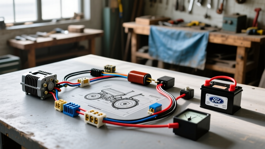
Introduction to the Ford 8N 12V Negative Ground Conversion
The Ford 8N tractor, produced between 1939 and 1952, originally left the factory equipped with a 6-volt, positive-ground electrical system utilizing a belt-driven generator and a voltage regulator. While historically accurate, the 6V system is notoriously prone to voltage drop, dim lighting, and sluggish cold-weather cranking. Consequently, the Ford 8N wiring diagram 12V conversion has become the gold standard for restorers and working farmers alike. Transitioning to a 12-volt, negative-ground architecture allows for the integration of a modern internally regulated alternator, brighter halogen or LED work lights, and reliable electronic ignition modules.
This comprehensive walkthrough dissects the complete 12V negative-ground wiring schematic for the Ford 8N. We will cover battery cable routing, Delco 10-SI alternator pinouts, ammeter polarity reversal, and the critical ignition coil ballast requirements. Whether you are working with an early '39-'50 front-mount distributor or a later '50-'52 side-mount distributor, this guide provides the exact AWG specifications, wire color codes, and terminal configurations required for a reliable, fire-safe electrical overhaul.
Core Components of the 12V Negative Ground System
Before cutting or splicing a single wire, it is imperative to understand the fundamental hardware swaps required for this conversion. You cannot simply drop a 12V battery into an 8N and expect the OEM components to survive.
- Alternator Swap: The OEM 6V generator and external cutout relay must be removed. The industry standard replacement is the GM Delco 10-SI 63-amp alternator. It is compact, internally regulated, and features a simple 3-wire or 1-wire hookup.
- Ignition Coil and Ballast Resistor: The OEM 6V coil has an internal resistance of approximately 1.2 to 1.5 ohms. If subjected to 14.4V from a 12V alternator, it will draw over 9 amps, instantly burning out the breaker points and melting the coil windings. You must either install a dedicated 12V coil (3.0 ohms internal resistance) or wire a 1.5-ohm ceramic ballast resistor in series with the OEM 6V coil.
- Starter Solenoid: The original 6V solenoid is a "grounded base" type, meaning the case grounds through the mounting bracket. A 12V conversion requires an "isolated ground" solenoid (commonly used on Ford tractors and older F-series trucks) where the ground is triggered via a dedicated terminal, preventing parasitic draws and accidental cranking.
- Ammeter Polarity: The OEM loop-type ammeter will function on a 12V system, but the leads must be swapped. If wired as a positive ground, the gauge will read "Discharge" when the alternator is charging the battery.
Step-by-Step Wiring Diagram Walkthrough
1. Battery, Ground Cables, and Starter Routing
The foundation of the 12V negative ground system begins at the battery. The negative terminal must be grounded to the tractor frame or engine block, while the positive terminal feeds the starter circuit.
- Run a 1/0 AWG (or minimum 2 AWG) pure copper welding cable from the battery positive terminal to the "BAT" terminal on the new isolated-ground starter solenoid.
- Connect a 1/0 AWG ground cable from the battery negative terminal to a clean, unpainted cast-iron surface on the engine block or transmission housing. Use a star washer to bite through the paint and ensure less than 0.1 ohm of resistance.
- Run a 2 AWG cable from the "STRT" terminal on the solenoid directly to the starter motor post.
2. Ammeter and Main Power Feed Integration
The Ford 8N dash features a single ammeter that monitors the entire electrical system. In a 12V setup, the ammeter acts as a series shunt for the main power feed.
- From the "BAT" terminal on the starter solenoid, run a 10 AWG red wire up to the dash. Connect this to the post on the back of the ammeter marked "GEN" (or the left post, depending on the gauge manufacturer).
- From the opposite ammeter post (marked "BAT"), run a 10 AWG red wire to the ignition switch "BAT" terminal, and splice in a secondary 10 AWG red wire that routes to the alternator's main output terminal.
- Crucial Note: Because we are using a negative ground, current flows into the battery's positive terminal during charging. Ensure the ammeter needle swings to the right (+) when the tractor is running at 1200 RPM.
3. Delco 10-SI Alternator Pinout and Exciter Circuit
The Delco 10-SI alternator features a 2-pin rectangular connector on the rear housing. Understanding these pins is the most common failure point in 8N conversions.
- Terminal BAT (Large threaded post): Connects directly to the battery positive via the 10 AWG red wire mentioned above. This post supplies the rotor field current and outputs the charging voltage. Torque the retaining nut to 50 in-lbs.
- Terminal 1 (Exciter/Sense): This terminal requires a switched 12V signal to "wake up" the internal voltage regulator. Run a 14 AWG wire (typically yellow or red with a stripe) from the ignition switch "IGN" terminal, through a 194-bulb dash indicator light (which acts as a resistor), and into Terminal 1. When the key is ON, the bulb illuminates, providing the initial 200mA excitation current. Once the alternator begins charging, voltage equalizes on both sides of the bulb, and it turns off.
- Terminal 2 (Voltage Sense): This terminal tells the regulator what the battery voltage actually is. For the most accurate charging profile, run a 14 AWG red wire from Terminal 2 directly to the main power feed at the back of the ammeter. Do not simply jumper Terminal 2 to the BAT post on the alternator, as voltage drop across the long tractor harness will cause the battery to undercharge.
4. Ignition Coil and Ballast Resistor Configuration
Whether your 8N has the front-mount distributor (square cap, coil mounted directly on top) or the side-mount distributor (round cap, coil on the dash), the 12V ignition wiring logic remains identical.
- Run a 14 AWG wire from the ignition switch "IGN" terminal to one side of the 1.5-ohm ceramic ballast resistor.
- From the opposite side of the ballast resistor, run a 14 AWG wire to the positive (+) terminal of the ignition coil. (Note: In a negative ground system, the coil positive connects to the switched power, and the coil negative connects to the distributor points).
- Run a 14 AWG black wire from the negative (-) terminal of the coil to the distributor breaker points terminal. Ensure the condenser is wired in parallel to this circuit to prevent arcing across the points.
Ford 8N 12V Wiring Specification Chart
| Circuit Description | AWG Size | Wire Color Code | Connection Points | Torque / Notes |
|---|---|---|---|---|
| Battery to Solenoid | 1/0 AWG | Red (or bare copper) | BAT (+) to Solenoid BAT | 10-12 ft-lbs on post nut |
| Engine Ground Strap | 1/0 AWG | Black | BAT (-) to Engine Block | Use star washer, clean cast iron |
| Solenoid to Starter | 2 AWG | Red | Solenoid STRT to Starter Post | Protect with heat shrink loom |
| Main Dash Feed (Ammeter) | 10 AWG | Red | Solenoid BAT to Ammeter to IGN Switch | Use 1/4" ring terminals, crimp & solder |
| Alternator Main Output | 10 AWG | Red | Alt BAT Post to Ammeter/IGN Feed | 50 in-lbs on Alt nut, use lock washer |
| Alternator Exciter (Pin 1) | 14 AWG | Yellow | IGN Switch to Dash Bulb to Alt Pin 1 | Requires 194 bulb resistor in line |
| Alternator Sense (Pin 2) | 14 AWG | Red w/ White Stripe | Alt Pin 2 to Ammeter BAT Post | Do not jumper to local Alt BAT post |
| Ignition Feed (Pre-Resistor) | 14 AWG | Red w/ Black Stripe | IGN Switch to Ballast Resistor | Mount resistor away from fuel lines |
| Coil to Distributor Points | 14 AWG | Black | Coil (-) to Distributor Terminal | Ensure wire does not ground to cap |
Troubleshooting Common 12V Conversion Failures
Even with a perfect schematic reference, real-world tractor environments introduce vibration, corrosion, and aftermarket part inconsistencies. Use this decision tree to diagnose the most frequent 8N 12V conversion issues.
Symptom: The Dash "Charge" Indicator Light Never Turns Off
- Cause A: Broken exciter wire or blown dash bulb. If the 194 bulb is blown, Terminal 1 receives no initial excitation current, and the alternator will not "turn on." Fix: Test for 12V at Terminal 1 with the key ON. Replace the bulb or repair the 14 AWG yellow wire.
- Cause B: Alternator diode trio failure. If the internal diodes are shorted, the alternator will backfeed power to Terminal 1, keeping the dash light illuminated even when the key is off. Fix: Disconnect the 2-pin plug. If the light goes out but battery drains overnight, replace the alternator.
Symptom: Ignition Points Burn Out Within 5 Hours of Operation
- Cause: Missing or bypassed ballast resistor. Without the 1.5-ohm resistance, the 12V system pushes excessive amperage through the points, causing rapid tungsten ablation and eventual welding of the contacts. Fix: Verify voltage at the coil (+) terminal while the engine is running. It should read between 7.5V and 9.0V. If it reads 13.5V+, you have bypassed the ballast resistor. Install a ceramic resistor immediately.
Symptom: Ammeter Reads Deep Discharge While Tractor is Running
- Cause: Ammeter polarity reversal or 1-wire alternator backfeed. If the ammeter wires were not swapped during the transition from positive to negative ground, the gauge will read backwards. Fix: Swap the two 10 AWG wires on the back of the ammeter. Additionally, ensure you are not using a cheap 1-wire alternator without an internal blocking diode, which can cause parasitic draw through the ammeter shunt when the tractor is parked.
Authoritative References and Standards
When executing high-current modifications on vintage agricultural equipment, adhering to established electrical standards is critical for fire prevention and system longevity. The wire gauge recommendations and alternator pinout data in this guide are derived from the following authoritative resources:
- SAE J1128 Standard: Specifies the requirements for low-tension primary cable used in automotive and agricultural applications, including insulation temperature ratings and AWG current-carrying capacities. Reference: SAE International J1128.
- Delco Remy 10-SI Service Manual: The definitive OEM documentation for the wiring, testing, and rebuilding of the 10-SI and 12-SI series alternators, including exact terminal excitation thresholds. Reference: Delco Remy Technical Archives.
- Ford Tractor Electrical Archives: Historical schematics and community-verified conversion data for the 9N, 2N, and 8N series tractors, specifically detailing front-mount vs. side-mount distributor nuances. Reference: Yesterday's Tractors 8N Electrical Forum.
By strictly following this Ford 8N wiring diagram 12V walkthrough, you will eliminate the chronic electrical gremlins of the original 6V system, resulting in a tractor that starts instantly, charges reliably at idle, and powers modern implements without voltage drop.