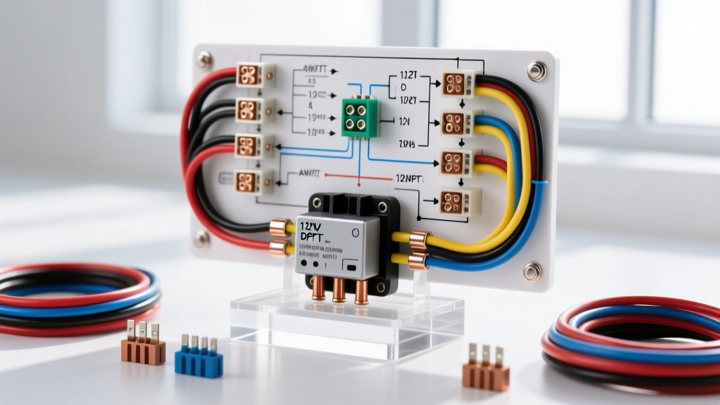
Advanced Architecture: The DPDT Relay in 12V DC Systems
In advanced automotive electrical design, the Double Pole Double Throw (DPDT) DC relay is the cornerstone of bidirectional motor control and dual-circuit isolation. Unlike standard Single Pole Single Throw (SPST) Bosch-style relays that merely switch a single high-current load on and off, a DPDT relay contains two completely isolated internal switching poles, each with a Common, Normally Open (NO), and Normally Closed (NC) contact. This internal architecture allows a single low-current trigger signal to simultaneously manipulate two separate high-current circuits, making it the ideal electromechanical alternative to solid-state H-Bridge motor drivers for applications like power windows, linear actuators, central locking systems, and reversible hydraulic pumps.
When designing or troubleshooting a dc relay wiring diagram dpdt configuration, automotive engineers must account for inductive kickback, contact arcing, and inrush current stall loads. A standard 12V DC motor can draw 5 to 7 times its continuous running current during startup (stall current). If the relay contacts are not rated for this inductive inrush, micro-welding will occur, leading to catastrophic failure modes where the relay remains stuck in the closed position.
Internal Pinout Configuration & DIN 72552 Mapping
While standard 4-pin and 5-pin automotive relays use the familiar 30, 85, 86, 87, and 87a designations, the 8-pin DPDT relay expands this nomenclature to accommodate the second pole. Below is the definitive pinout matrix based on DIN 72552 and ISO 8-pin automotive standards.
| Pin Number | Function | Internal State (De-energized) | Internal State (Energized) | Typical OEM Wire Color |
|---|---|---|---|---|
| 85 | Coil Ground | N/A | N/A | Black (BLK) |
| 86 | Coil +12V Trigger | N/A | N/A | Yellow (YEL) or Pink (PNK) |
| 30 | Pole 1 Common | Connected to 87a | Connected to 87 | Red (RED) or Orange (ORG) |
| 87 | Pole 1 Normally Open | Open | Connected to 30 | Dark Blue (DK BLU) |
| 87a | Pole 1 Normally Closed | Connected to 30 | Open | Brown (BRN) |
| 30b | Pole 2 Common | Connected to 87c | Connected to 87b | Black (BLK) or Ground |
| 87b | Pole 2 Normally Open | Open | Connected to 30b | Brown (BRN) |
| 87c | Pole 2 Normally Closed | Connected to 30b | Open | Dark Blue (DK BLU) |
Core Application: Polarity Reversing (The Electromechanical H-Bridge)
The most powerful application of a DPDT DC relay in automotive wiring is polarity reversal. By utilizing a 'crossover' wiring topology, a single DPDT relay can reverse the direction of a 12V DC motor without requiring complex solid-state logic or dual relays. This is heavily utilized in aftermarket off-road winch controls, convertible top hydraulics, and power tailgate actuators.
Step-by-Step Polarity Reversal Wiring Guide
To achieve safe bidirectional control without creating a dead short across the battery terminals during the transition phase, the crossover must be wired precisely as follows:
- Power Feed: Connect constant fused +12V to Pin 30 (Pole 1 Common).
- Ground Feed: Connect a dedicated chassis ground (minimum 12 AWG) to Pin 30b (Pole 2 Common).
- Motor Leg A: Connect Motor Wire 1 to Pin 87 (Pole 1 NO) and Pin 87c (Pole 2 NC).
- Motor Leg B: Connect Motor Wire 2 to Pin 87a (Pole 1 NC) and Pin 87b (Pole 2 NO).
- Trigger Circuit: Connect Pin 86 to a switched +12V source (e.g., dashboard toggle switch). Connect Pin 85 to ground.
Operational Logic: When the coil is de-energized, Pin 30 (+12V) feeds Pin 87a (Motor Leg B), while Pin 30b (Ground) feeds Pin 87c (Motor Leg A). The motor spins in Direction 1. When the trigger is applied, the internal contacts throw simultaneously. Pin 30 (+12V) now feeds Pin 87 (Motor Leg A), and Pin 30b (Ground) feeds Pin 87b (Motor Leg B). The polarity is instantly reversed, spinning the motor in Direction 2.
Advanced Circuit Protection: Flyback Diodes & Snubbers
An often-overlooked aspect of the dc relay wiring diagram dpdt is coil suppression. A standard automotive relay coil possesses an inductance of roughly 50mH to 150mH. When the trigger circuit (Pin 86 or 85) is opened, the collapsing magnetic field induces a massive reverse Electromotive Force (EMF). According to the formula V = -L(di/dt), this voltage spike can exceed 100V DC for a fraction of a millisecond. If the relay is triggered by a sensitive solid-state ECU driver or a BCM (Body Control Module), this spike will instantly destroy the internal driver transistor.
The Solution: Install a flyback diode across the coil terminals. A 1N5408 (3 Amp) or 1N4007 (1 Amp) rectifier diode is required. Wire the Cathode (silver stripe) to Pin 86 (+12V) and the Anode to Pin 85 (Ground). This creates a localized recirculation loop that safely clamps the inductive spike to approximately 0.7V, protecting upstream automotive modules. For high-speed switching applications where a diode slows down the relay drop-out time, use a Zener diode (e.g., 15V) in series with the standard rectifier diode to allow a faster coil collapse while still protecting the ECU.
Wire Gauge (AWG) & Connector Selection Matrix
Adhering to SAE J1128 standards for low-voltage automotive cable is critical to prevent voltage drop and thermal runaway. The following matrix dictates the minimum cross-sectional area based on the continuous load of the DC motor or accessory.
| Continuous Load (Amps) | Stall/Inrush Current (Est.) | Minimum Wire Gauge (AWG) | Max Length (10ft round trip) | Recommended Connector |
|---|---|---|---|---|
| 10A | 30A - 50A | 14 AWG | 15 Feet | Metri-Pack 280 |
| 20A | 60A - 100A | 12 AWG | 10 Feet | Metri-Pack 280 / 630 |
| 30A | 90A - 150A | 10 AWG | 8 Feet | Deutsch DT Series |
| 40A+ | 120A+ | 8 AWG | 6 Feet | Deutsch DT / Ring Terminal |
Expert Note: When terminating 10 AWG or 8 AWG wire to the relay spades, always use closed-barrel, nylon-insulated crimp terminals. Apply a heat-shrink adhesive lining to seal out moisture and prevent galvanic corrosion in the engine bay. Torque ring terminal connections to the battery or chassis ground to the manufacturer's specification (typically 10-15 Nm for M8 studs).
Real-World Failure Modes & Oscilloscope Diagnostics
When a DPDT reversing circuit fails, technicians often replace the motor when the fault actually lies in relay contact degradation. Due to the high inductance of DC motors, breaking the circuit under load generates a sustained DC arc across the relay contacts. Over time, this arc vaporizes the silver-tin oxide contact material, increasing contact resistance and causing severe voltage drops under load.
Diagnostic Procedure: Connect an oscilloscope across the motor terminals. Command the relay to switch. A healthy DPDT relay will show a clean square wave transition with minimal bounce (under 2 milliseconds). If the trace reveals high-frequency oscillation lasting longer than 5ms, or if the peak voltage delivered to the motor drops below 10.5V during the initial stall phase, the internal relay contacts are pitted and suffering from micro-arcing. In these instances, upgrading to a high-inrush Littelfuse automotive relay with tungsten-pre-charge contacts is mandatory to handle the inductive motor loads reliably.
References & Engineering Standards
- SAE International: SAE J2851 - Application Guide for Automotive Relays
- Texas Instruments: Relay Coil Suppression and Inductive Kickback Mitigation
- Littelfuse Automotive: Automotive Relay Application Notes and Derating Curves