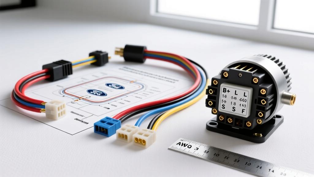
The Ford 2G Alternator: Understanding the Wiring and the 'Fire Hazard'
The Ford 2G alternator, introduced in the mid-1980s and utilized extensively through the early 1990s on models like the Foxbody Mustang, F-150, and Ranger, represents a pivotal but flawed era in OEM automotive electrical design. While it offered a respectable 65-amp to 75-amp output and introduced an integral voltage regulator, the 2G is infamous among automotive electricians for a critical factory defect: the main B+ output circuit. From the factory, Ford routed a 10 AWG wire with a fusible link directly from the alternator B+ post to the starter solenoid. Under continuous high-load conditions, this undersized wiring harness routinely overheats, melts the plastic casing, and causes catastrophic alternator fires.
This practical how-to guide covers the exact Ford 2G alternator wiring diagram, provides a safe, heavy-gauge installation protocol to eliminate the fire risk, and details the precise pinout configurations for the 3-wire regulator connector. Whether you are restoring a classic Foxbody or maintaining a 90s work truck, upgrading the 2G wiring is not optional—it is a mandatory safety procedure.
Ford 2G Alternator Pinout and Wire Color Specifications
Before cutting or splicing any wires, you must understand the specific circuits tied to the 2G alternator. The system relies on a heavy-gauge output post and a 3-pin plastic connector that dictates the regulator's behavior.
| Terminal / Pin | Function | OEM Wire Color | Recommended AWG Upgrade |
|---|---|---|---|
| B+ Post | Main Charging Output | Black/Orange (10 AWG) | 4 AWG (with 80A-100A Mega Fuse) |
| Pin A (Sense) | Battery Voltage Sense | Yellow/White | 14 AWG (Fused 5A) |
| Pin I (Ignition) | Regulator Turn-On / Dash Lamp | White | 14 AWG |
| Pin S (Stator) | Stator Feedback (Often Internal) | Green/Red | 14 AWG (If applicable) |
Note: On many later 2G applications, the 'S' (Stator) pin is tied internally to the alternator stator windings, and the external Green/Red wire is omitted from the harness. Always verify your specific vehicle's harness using a factory service manual or resources like Fordification's Alternator Tech Guide.
Tools and Materials Required for a Safe Installation
To properly rewire the 2G alternator and eliminate the OEM fire hazard, you must abandon the factory 10 AWG routing. Gather the following materials:
- Primary Wire: 4 AWG SAE J1128 battery cable (Red) for the B+ run. Reference the SAE J1128 Battery Cable Standard for high-temperature engine bay ampacity ratings.
- Overcurrent Protection: 80A or 100A ANL / Mega Fuse with an inline marine-grade fuse holder.
- Terminals: 4 AWG closed-loop ring terminals (3/8 inch stud size for the alternator B+ post, 5/16 inch for the battery/solenoid).
- Regulator Pigtail: Motorcraft 3-pin alternator connector pigtail (Part# WPT-446 or equivalent) with pre-crimped weather-pack seals.
- Tools: Hydraulic wire crimper, adhesive-lined marine heat shrink, wire loom, multimeter, and torque wrench.
Step-by-Step Ford 2G Alternator Wiring Installation
Step 1: Isolate the Electrical System and Remove OEM Wiring
Disconnect the negative battery terminal and isolate it. Locate the alternator B+ post. Unbolt the factory Black/Orange 10 AWG wire and the associated fusible link. Trace this wire back to the starter solenoid or main harness splice and remove it entirely. Do not attempt to reuse the factory 10 AWG B+ wire under any circumstances. The insulation on 30-year-old OEM wiring is brittle, and its current-carrying capacity is insufficient for modern aftermarket electrical loads (e.g., EFI conversions, high-wattage lighting, or aftermarket audio).
Step 2: Fabricate the 4 AWG Heavy-Gauge B+ Harness
Measure the distance from the alternator B+ post to the positive battery terminal (or the main junction block). Cut a length of 4 AWG red welding cable. Strip 5/8 inch of insulation from both ends. Slide a piece of adhesive-lined heat shrink over the wire, then crimp a 3/8 inch ring terminal onto the alternator end using a hydraulic crimper. Apply heat until the adhesive seals the wire strands. Repeat for the battery end, but terminate it with an inline ANL fuse holder before connecting to the battery positive post. The fuse must be located within 18 inches of the battery positive terminal to protect the entire cable run in the event of a short to ground.
Step 3: Re-pin and Replace the 3-Wire Regulator Connector
The plastic 3-pin connector on the 2G alternator is prone to cracking, and the internal spade terminals lose their tension over time, leading to voltage drops on the 'A' (Sense) circuit. If the 'A' circuit experiences resistance, the internal regulator will falsely read a low battery state and overcharge the system, boiling the battery. Cut off the old OEM plug and splice in the new Motorcraft pigtail. Use solder-seal heat shrink connectors for the splices. Route the Yellow/White (Sense) wire directly to a clean, fused 12V source at the battery or main fuse block to ensure the regulator reads true system voltage, bypassing any voltage drop caused by the factory ignition switch or under-dash wiring.
Step 4: Routing, Looming, and Torque Specifications
Route the new 4 AWG cable away from the exhaust manifolds and steering shaft. Secure the cable every 8 inches using UV-resistant zip ties and split wire loom. When attaching the 3/8 inch ring terminal to the alternator B+ post, ensure the mating surface of the alternator casing is free of corrosion. Torque the B+ nut to exactly 95-110 in-lbs. Overtightening will strip the soft aluminum threads on the alternator rear housing; undertightening will cause micro-arcing and localized melting.
Post-Installation Validation: Voltage Drop Testing
Do not assume the installation is successful simply because the battery is charging. You must perform a voltage drop test to verify the integrity of the new 4 AWG circuit. Set your multimeter to DC Volts. Place the red probe on the alternator B+ post and the black probe on the battery positive terminal. Start the engine and turn on all major electrical loads (headlights, HVAC blower on high, rear defroster). The multimeter should read a maximum voltage drop of 0.20V (200mV). If the reading exceeds 0.20V, you have high resistance in your crimps, the ANL fuse holder, or the terminal connections.
Troubleshooting Common 2G Charging System Failures
Even with a flawless heavy-gauge upgrade, the 2G alternator's internal regulator and brush assembly can exhibit specific failure modes. Use this decision tree to diagnose lingering issues:
| Symptom | Probable Cause | Diagnostic Fix / Action |
|---|---|---|
| Alternator output exceeds 15.5V | Open circuit or high resistance on Pin A (Yellow/White Sense wire). | Check continuity from Pin A to the battery positive. Repair or reroute the sense wire. |
| Dash charge lamp stays illuminated | Blown dash bulb, broken White (I) wire, or failed internal regulator. | Verify 12V at the White wire with key ON, engine OFF. If present, replace alternator/regulator. |
| Output drops below 12.5V under load | Worn carbon brushes or slipped slip-rings inside the alternator. | 2G brushes are replaceable but require soldering. For reliability, upgrade to a Ford 3G alternator (130A) using a Motorcraft conversion harness. |
| Whining noise through stereo system | Alternator diode ripple or poor chassis grounding. | Perform an AC voltage ripple test at the battery. If AC voltage exceeds 50mV, replace the alternator rectifier bridge. |
Expert Insight: The 3G Alternator Swap Alternative
While this guide details how to safely wire and install the OEM Ford 2G alternator, any seasoned automotive electrical technician will advise that the ultimate 'fix' for a 2G-equipped vehicle is swapping to the later Ford 3G alternator. The 3G (introduced in 1993) outputs 130 amps, utilizes a much safer internal B+ routing design that eliminates the external fire hazard, and features a superior voltage regulator. If you choose to retain the 2G for concours correctness or packaging constraints, adhering strictly to the 4 AWG upgrade and fused B+ protocol outlined above is non-negotiable for vehicle safety.