Understanding the Dodge Charging System Architecture
When troubleshooting or upgrading the electrical system in Dodge trucks and SUVs (such as the Ram, Dakota, and Durango), understanding the alternator wiring is critical. Over the decades, Chrysler and Dodge have transitioned through several alternator architectures. The most common setups you will encounter include the classic Chrysler external-regulator 'Round-Back' and 'Square-Back' alternators (pre-1990s), the internal-regulator Chrysler alternators (early 1990s), and the modern PCM-controlled Denso alternators (1998 to present).
This technical specification reference focuses on providing a simple Dodge alternator wiring diagram breakdown for the most prevalent systems. Whether you are dealing with a classic Mopar field circuit or a modern Pulse Width Modulated (PWM) Denso unit, having the exact OEM wire color codes, AWG requirements, and pinout configurations is essential for a reliable repair. For comprehensive testing standards, technicians should refer to Haynes Automotive Electrical Repair Manuals and Denso Automotive Alternator Specifications.
Modern PCM-Controlled Denso Alternator (1998–Present)
Starting in the late 1990s and continuing through the modern Hemi and Cummins eras, Dodge transitioned to Denso-manufactured alternators. Unlike older systems where the alternator regulated its own output based on an internal voltage reference, modern Dodge alternators are controlled directly by the Powertrain Control Module (PCM). The PCM monitors battery temperature, voltage, and electrical load, then sends a duty-cycle signal to the alternator's internal regulator.
Denso 2-Pin and 3-Pin Connector Pinout
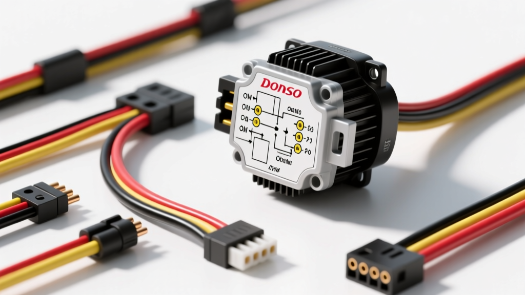
The wiring harness plug on a standard Dodge Denso alternator typically features a 2-pin or 3-pin connector. The 3-pin connector is the most common on heavy-duty applications (like the 5.9L and 6.7L Cummins Rams). Below is the schematic flow and pinout specification:
- Pin 1 (Generator Sense): Provides a direct battery voltage reference to the PCM. This wire usually routes to a fused ignition switch source or directly to the battery positive via the Integrated Power Module (IPM).
- Pin 2 (Generator Field): Carries the PWM control signal from the PCM to the alternator's internal voltage regulator. This is a low-voltage, low-current control circuit.
- Pin 3 (Lamp / ECU Communication): On some specific Denso variants, a third pin is used for the dashboard charge indicator lamp or LIN-bus communication, though many Dodge applications rely solely on the PCM for CAN-bus dash communication.
OEM Wire Color Codes and AWG Specifications
| Pin / Circuit | Function | OEM Wire Color (Typical) | Wire Gauge (AWG) | Connector Type |
|---|---|---|---|---|
| B+ Terminal | Main Battery Output | Red (Heavy Cable) | 6 AWG to 2 AWG | M8 Ring Terminal |
| Pin 1 (Sense) | Voltage Reference | Dark Green (DG) | 18 AWG | Weather-Pack Female |
| Pin 2 (Field) | PWM Control Signal | Dark Green / Orange (DG/OR) | 18 AWG | Weather-Pack Female |
| Case Ground | Alternator Chassis Ground | N/A (Bare Metal) | N/A | M8 / M10 Mounting Bolt |
Classic Chrysler 2-Wire Field Circuit (Pre-1990s)
If you are restoring a classic Dodge truck or working with an older Mopar V8, you will encounter the legendary Chrysler 'Square-Back' or 'Round-Back' alternators. These utilize a remarkably simple 2-wire field circuit that is highly favored by off-road and custom-fabrication enthusiasts due to its ease of bypass-wiring.
The classic setup uses two separate field terminals on the back of the alternator (often labeled 'FLD' and 'GND' or simply two spade terminals). One terminal receives switched 12V ignition power (often routed through a ballast resistor or the ignition switch), while the other terminal is grounded by the mechanical or electronic voltage regulator to complete the magnetic field circuit. The OEM wire colors for these field wires are typically Green and Blue. The heavy B+ output wire is typically a 10 AWG or 8 AWG red wire routing to the starter relay battery stud.
Wiring Harness, Torque, and Crimping Standards
When repairing or extending the wiring harness for any Dodge alternator, adhering to SAE J1113 standards for electrical component routing and crimping is vital to prevent voltage drops and electromagnetic interference (EMI).
- B+ Terminal Torque: The M8 nut securing the main output cable to the alternator B+ stud must be torqued to exactly 12–15 Nm (8.9–11 lb-ft). Overtightening will strip the copper stud; undertightening will cause arcing and melt the plastic insulator boot.
- Crimping Standards: Never use solder on the B+ ring terminal. Solder becomes brittle under high-vibration, high-heat alternator environments. Use a closed-barrel, adhesive-lined heat-shrink crimp terminal applied with a calibrated ratcheting crimp tool.
- Wire Routing: The PWM field wire (Dark Green/Orange) must be routed at least 4 inches away from high-tension ignition coils or injector harnesses to prevent inductive cross-talk, which can cause the PCM to misinterpret the field duty cycle and result in erratic charging voltages.
Real-World Failure Modes and Diagnostic Testing
A 'no-charge' or 'overcharge' condition on a Dodge Ram is rarely a failed alternator on the first guess. Modern Denso units are incredibly robust; the failure usually lies in the wiring harness, the PCM, or the battery temperature sensor. Use the following diagnostic decision tree:
Step 1: The Voltage Drop Test (B+ and Ground)
Before removing the alternator, test the heavy gauge wiring. Set your multimeter to DC Volts. Place the red probe on the alternator B+ stud and the black probe on the battery positive terminal. Start the engine and turn on all electrical accessories (headlights, blower motor, rear defroster).
- Acceptable Drop: Less than 0.2V.
- Failure Mode: If the drop exceeds 0.5V, the B+ cable is corroded internally, or the terminal crimp is failing. Replace with a custom 2 AWG or 4 AWG fine-strand welding cable.
- Ground Test: Place the red probe on the battery negative terminal and the black probe on the alternator case. A voltage drop greater than 0.1V indicates a poor engine-to-chassis ground strap, which is a notorious issue on 2003–2008 Dodge Rams.
Step 2: PCM Field Duty Cycle Analysis
If the heavy cables test perfectly, you must verify the PCM control signal. The PCM uses a 128Hz Pulse Width Modulated (PWM) signal on the Dark Green/Orange wire to command the alternator. Using an oscilloscope or a multimeter with a duty-cycle function, back-probe Pin 2 at the alternator connector with the engine running.
- Normal Operation: Duty cycle should range from 20% (low electrical load, high battery state-of-charge) to 85% (high electrical load, depleted battery). Target voltage at the battery should be between 13.8V and 14.4V, heavily dependent on the Battery Temperature Sensor (BTS) under the battery tray.
- Fault Code P2503 (Charging System Voltage Low): If the PCM commands an 85% duty cycle but system voltage remains below 13.0V, the internal Denso voltage regulator or the carbon brushes have failed. At this point, alternator replacement or a professional rebuild is required.
- Open Circuit (0% Duty Cycle): If there is no signal on the Dark Green/Orange wire, check for a broken wire between the alternator plug and PCM Connector C1 (Pin 59 on most 5.7L/5.9L applications). Dodge harnesses are prone to chafing near the passenger side valve cover where the harness rests against the aluminum cylinder head.
Step 3: Battery Temperature Sensor (BTS) Verification
Dodge vehicles utilize a BTS located under the battery tray to adjust charging voltage based on ambient and under-hood temperatures. Cold batteries require higher charging voltages (up to 14.8V), while hot batteries require lower voltages (down to 13.5V) to prevent gassing and thermal runaway. If your Dodge is overcharging and boiling the battery, do not immediately condemn the alternator. Inspect the BTS connector for acid corrosion and verify the 5V reference and signal return circuits back to the PCM.
Summary
Whether you are wiring a custom hot rod using a simple classic Chrysler 2-wire field setup or diagnosing a CAN-bus integrated Denso alternator on a modern Ram Cummins, precision is key. Always verify OEM wire colors, adhere to strict AWG and torque specifications, and rely on voltage-drop testing rather than simple continuity checks. By following this simple Dodge alternator wiring diagram reference, you ensure a reliable, noise-free, and highly efficient charging system capable of handling modern automotive electrical loads.