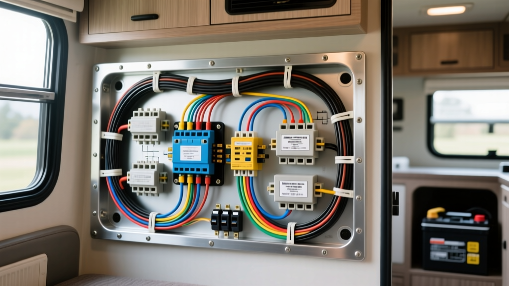
The 'House' vs. 'Chassis' Paradigm in RV Electrical Architecture
In the realm of recreational vehicles, motorhomes, and skoolie conversions, the electrical system is strictly divided into two isolated domains: the 'chassis' system and the 'house' system. The chassis network handles the automotive engine starting, alternator output, and ECU sensor arrays. The 'house' network powers the living quarters—encompassing interior lighting, water pumps, refrigeration, and HVAC systems. Many DIY converters and junior technicians begin their projects by searching for a basic wiring diagram for a house, mistakenly assuming that residential 120V AC National Electrical Code (NEC) principles will map directly to a 12V DC automotive environment. This fundamental misunderstanding is the leading cause of voltage drop, thermal runaway, and electrical fires in custom vehicle builds.
As an automotive electrical resource, Autoflow Wire emphasizes that translating residential architectural schematics into vehicular platforms requires a complete recalibration of Ohm's Law applications, wire gauge sizing, and overcurrent protection coordination. A residential home operates at 120V/240V AC, where high voltage keeps amperage low, allowing for long wire runs using relatively thin 14 AWG or 12 AWG copper. Conversely, a 12V DC house system demands massive amperage to deliver equivalent wattage, necessitating aggressive AWG scaling, specialized vibration-resistant terminations, and strict adherence to SAE and ABYC standards.
Translating Residential AC Concepts to 12V DC Automotive Standards
When adapting a basic wiring diagram for a house to a 12V DC motorhome coach, the primary adversary is voltage drop. The Society of Automotive Engineers (SAE J1128 Low Tension Primary Cable Standard) dictates that voltage drop in a 12V DC system should not exceed 3% for critical loads and 10% for non-critical lighting. In a residential AC diagram, a 1200W microwave drawing 10 Amps at 120V can safely utilize 14 AWG wire over a 50-foot run. In a 12V DC RV house system, that same 1200W microwave requires an inverter that will pull over 100 Amps from the battery bank. Attempting to use residential 14 AWG wire for this DC load will result in immediate wire melting and a catastrophic fire.
AWG Sizing and Voltage Drop Comparison Chart
The following specification table illustrates the severe divergence between residential AC wiring logic and automotive 12V DC requirements for common RV house loads. All DC calculations assume a maximum 3% voltage drop over a 15-foot one-way cable run at 12.6V (nominal battery resting voltage).
| Appliance Load | Wattage | 120V AC Amperage | Residential AC Wire (NEC) | 12V DC Amperage (Inverter Draw) | 12V DC Wire (SAE/ABYC) | DC Overcurrent Protection |
|---|---|---|---|---|---|---|
| LED Lighting Circuit | 60W | 0.5A | 14 AWG | 5.0A | 14 AWG | 10A ATO Blade Fuse |
| 12V Water Pump | 84W | N/A (DC Direct) | N/A | 7.0A | 12 AWG | 10A ATO Blade Fuse |
| 12V Compressor Fridge | 60W (Avg) | N/A (DC Direct) | N/A | 5.0A (Spike 15A) | 10 AWG | 20A Circuit Breaker |
| Induction Cooktop | 1800W | 15.0A | 12 AWG (20A Circuit) | 150.0A+ | 2 AWG | 175A ANL Fuse |
| A/C Unit via Inverter | 1500W | 12.5A | 12 AWG (20A Circuit) | 125.0A+ | 2 AWG | 150A Class T Fuse |
12V DC Distribution Bus Bar Architecture
In a standard residential house diagram, power is distributed via a centralized AC breaker panel using solid copper core wires pushed into spring-loaded or screw-terminal bus bars. In an automotive or RV house environment, vibration and thermal cycling will quickly loosen standard screw terminals, leading to arcing. Therefore, high-amperage DC distribution must utilize solid copper bus bars with bolted ring terminals.
For a robust RV house wiring harness, we specify 3/8-inch thick, tin-plated copper bus bars. Tin plating is critical; bare copper oxidizes rapidly in the humid, variable-temperature environment of a vehicle, increasing resistance at the junction point. All DC positive and negative returns must be routed to isolated, dedicated bus bars equipped with polycarbonate safety covers to prevent accidental short circuits from dropped tools.
Terminal Crimping and Torque Specifications
Automotive electrical failures frequently occur at the termination point rather than along the wire span. To ensure compliance with NFPA 1192 Standard on Recreational Vehicles, all wire terminations must utilize adhesive-lined heat shrink ring terminals. The adhesive lining melts during the heating process, sealing the wire barrel against moisture and preventing galvanic corrosion.
- Hex Crimp Profile: Use a hex-indent crimping tool for all AWG 8 through 2/0 battery cables. This provides a 360-degree cold weld that is superior to the standard indent crimp for high-vibration automotive environments.
- Torque Specs (M6 / 1/4-inch Hardware): 75 in-lbs (8.5 Nm)
- Torque Specs (M8 / 5/16-inch Hardware): 120 in-lbs (13.5 Nm)
- Torque Specs (M10 / 3/8-inch Hardware): 150 in-lbs (16.9 Nm)
Inverter/Charger Integration: AC to DC Bridging
The heart of any modern RV house wiring diagram is the Inverter/Charger, which bridges the 12V DC house battery bank and the 120V AC residential outlets inside the vehicle. When wiring a premium unit like the Victron MultiPlus 12/3000/120, the DC input studs require specific attention to thermal management.
Victron MultiPlus DC Input Pinout and Routing
The DC input on high-frequency inverters experiences massive ripple current. Using standard automotive SAE J1128 bare copper wire here is a critical error. The fine strands of bare copper will suffer from capillary action, drawing battery acid or ambient moisture up into the inverter's internal transformer, causing catastrophic failure. You must use UL 1426 Marine-Grade Tinned Copper wire (Type 3 stranding) for the final 6 feet of the inverter DC run.
- Positive DC Input (M8 Stud): Requires 2/0 AWG tinned copper cable. Must be protected by a 400A Class T fuse located within 18 inches of the positive battery terminal. Class T fuses are mandatory here due to their high AIC (Ampere Interrupting Capacity) rating of 20,000 Amps, which is required to safely interrupt lithium-ion battery short circuits.
- Negative DC Input (M8 Stud): Requires 2/0 AWG tinned copper cable routed to a dedicated 500A DC shunt for battery monitoring, then to the negative bus bar.
- Chassis Ground (M6 Stud): Requires 10 AWG green/yellow wire bonded to a clean, bare-metal point on the vehicle chassis to dissipate static buildup and provide a fault path for the AC grounding system.
Grounding and Chassis Bonding Protocols
One of the most debated topics when adapting a basic wiring diagram for a house to a vehicle is the DC negative return path. In traditional automotive wiring, the vehicle's steel chassis is used as the common ground return to save copper weight. However, the ABYC E-11 Electrical Systems Standard—widely adopted by high-end RV and expedition vehicle manufacturers—strictly prohibits using the chassis as a DC negative return path for house loads.
Stray DC currents traveling through the chassis can cause severe galvanic corrosion, destroying suspension components, brake lines, and the vehicle frame. Furthermore, modern vehicles utilize complex CAN-bus networks and pulse-width modulation (PWM) grounding for chassis sensors. Injecting 100+ Amps of house inverter return current into the chassis will induce electromagnetic interference (EMI), triggering phantom ECU fault codes and disrupting ABS or stability control modules. Therefore, a proper RV house wiring diagram must feature a fully isolated DC negative return network, where every load's negative wire runs back to a centralized, insulated negative bus bar, which is then tied directly to the battery bank via a dedicated shunt.
Summary of Best Practices for Vehicle-to-House Conversions
Successfully merging residential AC convenience with automotive DC reliability requires abandoning standard household wiring habits. By prioritizing ABYC-compliant tinned copper, hex-crimped adhesive terminations, isolated negative bus bars, and high-AIC Class T overcurrent protection, builders can create a 12V house system that is not only safe but capable of surviving the harshest vibrational and environmental stresses encountered on the road.