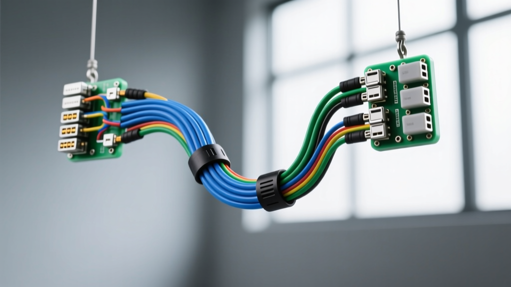
The Shift from Hand-Drawn Schematics to Digital Harness Design
Building a custom standalone engine harness for an LS swap, a dedicated track car, or a complex diesel deletion requires absolute precision. Hand-drawing schematics on poster board and routing wires by trial and error is a relic of the past. Modern wiring harness diagram software allows automotive electricians and DIY builders to map ECU pinouts, calculate loom diameters, generate physical assembly forms, and produce a comprehensive Bill of Materials (BOM) before cutting a single wire. By transitioning to a digital-first workflow, builders eliminate costly wiring errors, reduce harness weight, and ensure compliance with motorsport electrical standards.
This practical installation guide bridges the gap between digital schematic design and physical bench assembly. We will walk through configuring your software, mapping specific AWG requirements, and executing the physical build using industry-standard connectors and crimping techniques.
Phase 1: Configuring Your Wiring Harness Diagram Software
The first step in any custom ECU harness build is importing the manufacturer's pinout database into your chosen wiring harness diagram software. Whether you are using specialized CAD tools like Zuken E3.series, RapidHarness, or open-source alternatives, the software requires accurate connector definitions.
Defining Connector Families
Most modern standalone ECUs (such as the Haltech Elite 2500, MoTeC M150, or Holley Terminator X) utilize a mix of sealed automotive connectors. In your software environment, you must define the exact cavity count and terminal series:
- TE Connectivity (Amp) Superseal 1.5 Series: Common for older or secondary injector/ignition outputs.
- Aptiv Metri-Pack 150 and 280 Series: The industry standard for most sensor inputs, low-current grounds, and switched 12V outputs.
- Deutsch DT and DTM: Preferred for high-vibration environments and heavy-gauge power/ground distribution.
By defining these connectors in the software, the program automatically calculates the maximum wire fill capacity and suggests the appropriate conduit sizing (e.g., Techflex F6 3/4-inch braided sleeving or Tesa 51036 PET tape wrapping) based on the cumulative cross-sectional area of the routed wires.
Phase 2: Pinout Assignment and Wire Gauge (AWG) Mapping
Once the connectors are defined, the software allows you to map point-to-point connections. This is where electrical theory meets practical application. You must assign the correct American Wire Gauge (AWG) and wire insulation type based on the circuit's current draw and signal sensitivity. According to SAE J1128 standards, primary automotive cables like TXL (Thin Cross-Linked) and GXL (General Cross-Linked) are mandatory for under-hood environments due to their high temperature resistance (up to 125°C) and chemical resilience.
Haltech Elite 2500 Main Power & Sensor Pinout Matrix
Below is an example of how your wiring harness diagram software should map the critical circuits for a standalone V8 setup. This table represents the software's exported BOM and routing matrix.
| ECU Pin | Connector Cavity | Function | AWG | Wire Type | Color Code | Shielding |
|---|---|---|---|---|---|---|
| A1 | Cavity 1 (36-Pin) | Main Power (Ign Switched) | 14 AWG | TXL | Red | None |
| A2 | Cavity 2 (36-Pin) | ECU Main Power (Constant 12V) | 14 AWG | TXL | Red/White | None |
| A18 | Cavity 18 (36-Pin) | ECU Main Ground (Block) | 12 AWG | TXL | Black | None |
| B14 | Cavity 14 (12-Pin) | Crank Sensor Signal (+) | 20 AWG | TXL | Green | Shielded Twisted Pair |
| B15 | Cavity 15 (12-Pin) | Crank Sensor Signal (-) | 20 AWG | TXL | Green/Black | Shielded Twisted Pair |
| B16 | Cavity 16 (12-Pin) | Crank Sensor Shield Drain | 22 AWG | TXL | Bare Copper | Drain Wire |
| C4 | Cavity 4 (36-Pin) | Injector 1 (High Current) | 18 AWG | TXL | Yellow | None |
Phase 3: Physical Assembly Based on Software Output
The true power of wiring harness diagram software is its ability to generate a 'nail board' or form board diagram. This 1:1 scale printout is mounted to a wooden workbench, with finishing nails or 3D-printed pegs placed at exact routing nodes, connector endpoints, and breakout junctions. This ensures your physical harness matches the digital schematic perfectly, eliminating the 'guesswork' of harness length and bend radii.
Cutting, Stripping, and Crimping Protocols
When translating the software's cut list to the bench, precision is paramount. Follow these professional assembly steps:
- Wire Preparation: Cut wires to the exact lengths specified by the software's routing algorithm, adding exactly 1.5 inches for terminal crimping and heat shrink. Strip the insulation using precision wire strippers to avoid nicking the copper strands, which creates a stress riser and a potential failure point under engine vibration.
- Crimping Metri-Pack Terminals: As outlined in the Aptiv Automotive Connector Guidelines, a proper crimp requires a specific bell-mouth profile. The wire grip must secure the copper strands, while the insulation grip secures the TXL jacket. Use a ratcheting crimp tool (such as the TE Connectivity CERTI-CRIMP) to ensure the tool does not release until the exact compression force is achieved.
- Shielded Twisted Pair (STP) Termination: For Variable Reluctance (VR) crank and cam sensors, electromagnetic interference (EMI) from ignition coils will cause signal dropout. The software dictates STP wiring. Twist the signal wires at a rate of 6 to 8 twists per inch. The bare copper drain wire must be terminated only at the ECU sensor ground pin (e.g., Pin B16). Never ground the shield at the sensor end, as this creates a ground loop that induces noise into the signal circuit.
- Looming and Taping: Once all wires are laid on the form board and continuity is verified, bundle the harness. Wrap the harness in Tesa 51036 PET fleece tape for abrasion resistance and heat dissipation, then slide over Techflex F6 braided sleeving for the final aesthetic and mechanical protection.
Essential Tooling for Software-to-Bench Translation
- TE Connectivity CERTI-CRIMP Tool: Mandatory for Metri-Pack 150/280 series to ensure proper pull-out force retention.
- Hozan P-707 Wire Strippers: For precise stripping of 20-24 AWG sensor wires without damaging fine stranding.
- Fluke 87V Digital Multimeter: For executing the software's continuity and voltage-drop test matrix.
- Deutsch DT Wedgelocks: Ensure secondary retention wedges are inserted into all DT connectors to prevent terminal push-back.
Phase 4: Continuity Testing and Software Validation
Before wrapping the harness or installing it in the vehicle, you must execute the point-to-point test matrix generated by your wiring harness diagram software. This checklist ensures every pin matches the digital schematic.
Troubleshooting Common Assembly Failure Modes
Even with perfect software design, physical assembly errors occur. Use your multimeter to check for these specific failure modes:
- Pin Push-Back: When mating a connector to the ECU, a terminal that was not fully seated in the plastic housing will push backward, resulting in an open circuit. Fix: Perform a 'tug test' on every wire after crimping and inserting it into the connector housing. Listen for the distinct tactile click of the terminal locking tang engaging.
- Shield Drain Shorts: If the bare copper drain wire of an STP cable accidentally touches a 12V power wire or chassis ground along the loom, the ECU will read erratic sensor data. Fix: Use heat shrink tubing with an adhesive-lined inner wall (dual-wall polyolefin) to seal the drain wire termination at the sensor pigtail.
- Voltage Drop on Ground Circuits: The software may specify 14 AWG for ECU power, but if the ground path relies on a corroded engine block, the ECU will experience brownouts during starter cranking. Fix: Ensure the 12 AWG ECU ground wire (Pin A18) is terminated to a dedicated, clean stud on the engine block, and verify voltage drop across the ground circuit is less than 0.05V during simulated cranking loads.
Conclusion
Integrating wiring harness diagram software into your custom ECU swap workflow transforms a chaotic, error-prone process into a repeatable, professional-grade manufacturing operation. By strictly adhering to the software's AWG mapping, shielding requirements, and connector definitions, you ensure your vehicle's nervous system is as reliable as the engine it controls. For further reading on motorsport wiring standards and high-temperature insulation metrics, consult the Bosch Motorsport Engineering Guidelines to elevate your harness builds to FIA-compliant levels.