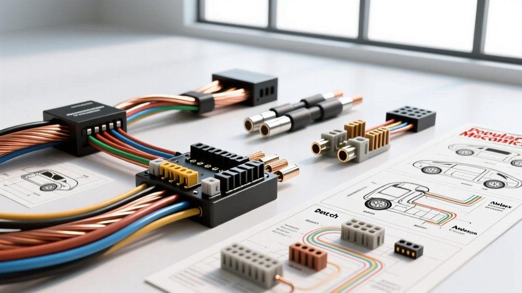
Why OEM Wiring Diagrams Fail on the Track
When transitioning a street vehicle into a dedicated track car, relying on a factory OEM schematic is a critical mistake. Street car diagrams are engineered for cost-efficiency, multiplexed CAN-bus body control modules, and noise reduction. In contrast, a dedicated race car wiring diagram prioritizes point-to-point reliability, centralized power distribution, rapid trackside troubleshooting, and strict compliance with sanctioning body safety rules. OEM harnesses utilize PVC-insulated wire that becomes brittle at sustained 105°C, whereas professional race harnesses specify MIL-W-22759/16 Tefzel wire, capable of withstanding 200°C engine bay temperatures without melting or off-gassing toxic fumes.
In this product comparison and selection guide, we evaluate the top universal and custom race harness systems on the market, analyzing their diagram structures, wire color codes, and technical specifications to help you select the right electrical foundation for your build.
Top Race Car Wiring Harness Systems Compared
The quality of a harness is only as good as the documentation supporting it. A professional race car wiring diagram must clearly map out fuse block assignments, relay trigger logic, and bulkhead pass-throughs. Here is how the industry leaders compare.
1. Painless Performance: Pro-Series & Track Harnesses
Painless Performance is a staple in circle track and drag racing. Their Pro-Series diagrams are renowned for their logical color-coding and centralized ATO fuse block layouts.
- Diagram Structure: Painless diagrams separate the chassis harness from the engine harness, utilizing a dedicated 12-pin or 21-pin bulkhead connector. This allows the front clip to be removed in minutes for tube-frame cars.
- Color Code Standard: They strictly adhere to standard hot-rod color codes: Red for constant 12V battery feed, Pink for ignition-switched 12V, Yellow for starter solenoid triggers, and Black for chassis grounds.
- Best For: Sportsman drag racers, dirt track modifieds, and time-attack builds requiring a robust, easily traceable, and heavily fused system.
2. Ron Francis Wiring: Bare Bones & Express Systems
Ron Francis takes a minimalist, weight-saving approach. Their diagrams are less cluttered than Painless, focusing heavily on heavy-gauge primary feeds and eliminating redundant circuits not needed in a race environment.
- Diagram Structure: The diagrams emphasize high-current paths. You will see detailed schematics for 4 AWG and 2 AWG alternator and starter feeds, integrating high-amperage marine-grade mega fuses (150A-250A) directly at the battery distribution block.
- Connector Strategy: Ron Francis diagrams frequently specify GM-style Weather-Pack connectors for under-hood sensors due to their wide availability and ease of crimping with standard tools.
- Best For: Budget-conscious track day cars, vintage trans-am restomods, and builders who prefer to wire auxiliary switches (fuel pumps, cooling fans) manually on a custom switch panel.
3. Howell Electrical: Custom EFI Race Harnesses
When your build relies on a complex standalone ECU (like a Holley Terminator X, MoTeC M1, or Haltech Elite), Howell Electrical provides the most sophisticated ECU-specific race car wiring diagrams in the industry.
- Diagram Structure: Howell diagrams are highly technical, detailing exact ECU pinouts, sensor shielding requirements, and CAN-bus termination nodes. They map out shielded twisted-pair wiring for Variable Reluctance (VR) crank and cam sensors to prevent electromagnetic interference (EMI) from high-output ignition systems.
- Wire Specs: They exclusively use MIL-SPEC Tefzel wire and cross-linked polyethylene (XLPE) for high-vibration zones.
- Best For: Professional road racing, endurance racing, and high-end EFI swaps where ECU data logging and sensor integrity are non-negotiable.
FIA Master Kill Switch Diagram Requirements
If you are building a car for SCCA, FIA, or NASA sanctioned events, your race car wiring diagram must include a compliant master electrical cut-off switch. According to FIA Appendix J, Article 277, the switch must interrupt all electrical circuits, including the ignition, fuel pumps, and lights.
A common, dangerous mistake found in amateur diagrams is failing to isolate the alternator. If the battery is disconnected but the alternator remains connected to the ignition system, the engine will continue to run via self-excitation. A compliant race diagram utilizes a 6-terminal rotary kill switch:
- Terminals 1 & 2 (Heavy Duty): Interrupts the main battery positive feed (using 1/0 AWG or 2 AWG cable).
- Terminals 3 & 4 (Low Current): Interrupts the alternator exciter wire (typically 14 AWG or 16 AWG). When the switch is turned off, this circuit opens, dropping the alternator’s voltage output to zero and killing the engine.
- Terminals 5 & 6 (Optional/Accessory): Used to trigger a fire suppression system or discharge a safety timer relay.
Race Circuit Wire Gauge & Specification Chart
Selecting the correct American Wire Gauge (AWG) is critical to prevent voltage drop under sustained high-RPM loads. The following chart outlines the baseline specifications found in professional race car wiring diagrams, referencing SAE J1128 standards for low-tension primary cable.
| Circuit Type | Recommended AWG | Standard Race Color Code | Connector / Termination |
|---|---|---|---|
| Starter Motor & Battery Feed | 1/0 AWG or 2 AWG | Red (with heat shrink) | Ring Terminal (Crimped & Adhesive-lined) |
| Alternator Output (High Amp) | 4 AWG or 8 AWG | Red | Ring Terminal / Mega Fuse Block |
| Ignition Box / ECU Main Power | 10 AWG | Red (Constant) / Pink (Switched) | Deutsch DT (4-way) or Weather-Pack |
| Fuel Pump (In-tank / Inline) | 12 AWG | Orange or Purple | Weather-Pack (Sealed) |
| Cooling Fans / Water Pump | 12 AWG or 14 AWG | Blue | Relay Spade / Ring Terminal |
| Sensors (TPS, MAP, IAT) | 18 AWG or 20 AWG | Signal: Yellow / Ground: Black | Deutsch DT or ECU-specific OEM plug |
| VR Crank/Cam Sensors (Shielded) | 22 AWG (Shielded Pair) | Twisted Pair (Shield drained at ECU) | Metri-Pack 150 or Sealed ECU Plug |
| CAN-Bus High / Low | 22 AWG or 24 AWG | CAN-H: White / CAN-L: Blue | Twisted Pair with 120Ω Resistors |
High-Vibration Connector Protocols
The most meticulously planned race car wiring diagram will fail if the wrong connectors are used in high-vibration zones. Street cars rely heavily on push-lock plastic connectors that loosen under harmonic engine vibration.
Professional race diagrams specify Deutsch DT series connectors for all engine bay and undercarriage sensors. Deutsch connectors utilize solid copper contacts crimped with an M22520/5-01 indent crimper, secured by a silicone grommet and a secondary locking wedge. Expert Warning: Never solder connections on a race car. Solder wicks up the copper strands, creating a rigid fulcrum point. Under constant engine vibration, the wire will fatigue and snap exactly at the edge of the solder joint. Always use high-quality, ratcheting indent crimpers.
Sensor Shielding and ECU Grounding Strategy
Modern standalone ECUs process millivolt signals from oxygen sensors and knock sensors. If your race car wiring diagram does not account for Electromagnetic Interference (EMI) from MSD ignition coils and high-output alternators, your engine will suffer from phantom knock retard and erratic fuel trims.
Shielding Protocol: Shielded cables must be used for all VR sensors and low-voltage analog signals. The metallic shield braid must be grounded only at the ECU sensor ground pin, never at the chassis or sensor body. Grounding both ends creates a ground loop, turning the shield into an antenna that amplifies EMI rather than blocking it.
Grounding Strategy: Unlike OEM diagrams that scatter ground points across the chassis, a race diagram utilizes a centralized Single Point Grounding (SPG) bus bar for all ECU and sensor grounds. The engine block must be tied to the chassis using a minimum 2 AWG flexible copper braid strap to ensure the starter motor's massive current draw does not back-feed through the ECU ground circuits.
Final Selection Advice
When choosing a harness and studying its accompanying race car wiring diagram, align your choice with your racing class rules and ECU complexity. For carbureted, points-ignition circle track cars, a Painless Performance kit offers the best balance of price and trackside serviceability. For complex, fuel-injected endurance cars requiring CAN-bus integration and MIL-SPEC reliability, investing in a custom Howell or Haltech harness with detailed, ECU-specific pinout diagrams is mandatory for finishing the race. Always verify your master kill switch logic against your specific sanctioning body's rulebook before your first technical inspection.