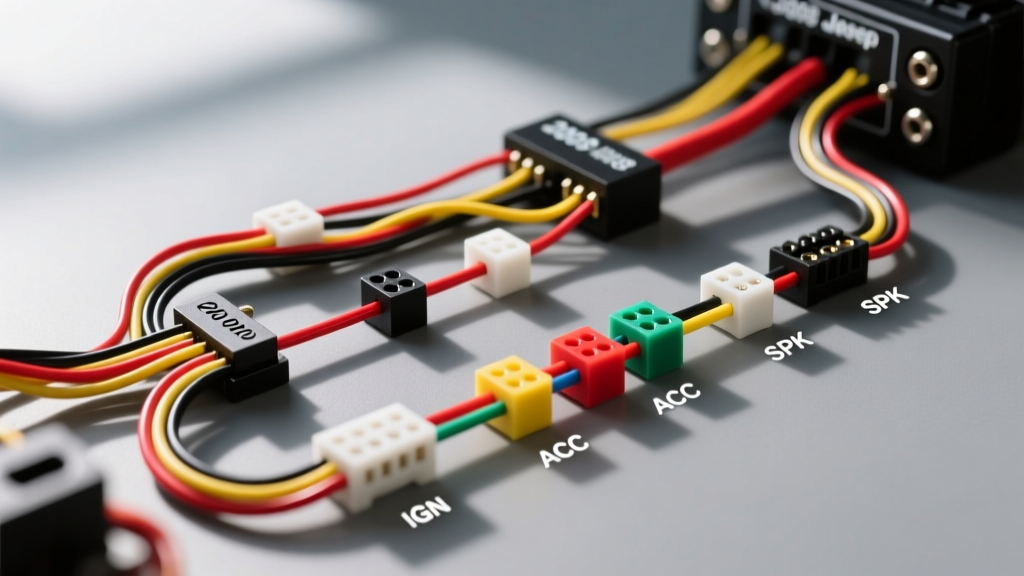
Introduction to the 2008 JK Audio Architecture
The 2008 Jeep Wrangler (JK generation) represents a transitional era in Chrysler automotive electrical systems. While it retains the traditional 22-pin Chrysler radio connector for base audio models, it also introduces deeper integration with the Controller Area Network (CAN bus) for body control functions, steering wheel controls, and accessory delay. When diagnosing audio failures or installing aftermarket head units, relying on a generic 2008 Jeep Wrangler stereo wiring diagram without understanding the underlying logic flow will lead to misdiagnosed grounds, blown internal amplifiers, and CAN bus communication faults.
This guide utilizes a step-by-step troubleshooting flow designed for automotive electrical technicians and advanced DIYers. We will trace the circuit from the battery to the speaker cones, utilizing specific AWG ratings, OEM wire color codes, and digital multimeter (DMM) testing protocols.
Phase 1: Primary Power and Ground Verification
Before testing speaker outputs or data lines, you must verify the integrity of the primary power circuit. The 2008 JK base stereo utilizes a standard 22-pin Chrysler connector. The power and ground circuits are the most common failure points due to dash vibration and corrosion.
OEM 22-Pin Connector Pinout Reference
| Pin | Function | OEM Wire Color | AWG | DMM Expected Value |
|---|---|---|---|---|
| 1 | Constant 12V+ (Battery) | Red/White | 16 AWG | 12.2V - 12.6V (Key Off) |
| 2 | Switched 12V+ (Ignition) | Pink/White | 16 AWG | 12.0V+ (Key ON/RUN) |
| 11 | Chassis Ground | Black/Light Green | 16 AWG | < 0.05 Ohms to chassis |
| 13 | Illumination / Dimmer | Dark Green/Orange | 18 AWG | 12V (Parking Lights ON) |
Diagnostic Step: Voltage Drop Testing
- Set your DMM to DC Voltage (20V range).
- Constant Power Test: Place the red probe on Pin 1 (Red/White) and the black probe on a known good bare metal chassis point. If you read below 11.5V, trace the Red/White wire back to the Totally Integrated Power Module (TIPM) under the hood. Check for corrosion at the TIPM connector, a known issue on 2007-2010 JKs.
- Ground Integrity Test: Switch the DMM to Ohms (Ω). Place one probe on Pin 11 (Black/Light Green) and the other on a bare metal dash brace. A reading above 0.5 Ohms indicates a compromised ground. Clean the grounding stud behind the passenger side kick panel or run a new 14 AWG ground wire directly to the chassis.
Phase 2: Step-by-Step Troubleshooting Decision Tree
Use the following symptom-based decision tree to isolate electrical faults within the 2008 Wrangler's audio circuit.
Symptom A: Aftermarket Head Unit Powers On, But Shuts Off During Engine Crank
- Cause: The ignition circuit (Pin 2) is wired to an accessory circuit that drops voltage during the starter solenoid engagement, or the head unit lacks adequate internal capacitance.
- Diagnostic Action: Monitor Pin 2 (Pink/White) with the DMM while an assistant cranks the engine. If voltage drops below 9V, the circuit is faulty.
- Resolution: Verify the Pink/White wire connection at the ignition switch harness behind the steering column. If using an aftermarket harness adapter, ensure it is tapped into a true 'Run/Start' ignition source, not a purely 'Accessory' source that cuts out during crank.
Symptom B: Head Unit Powers On, But No Audio Output (Base System)
- Cause: Blown internal head unit amplifier IC, shorted speaker wire touching the chassis, or incorrect adapter harness pin mapping.
- Diagnostic Action: Disconnect all speaker wires at the head unit. Power the unit on and test the RCA pre-outs or use an audio probe on the speaker output wires. If the unit goes into 'Protect' mode immediately upon power-up with no speakers connected, the internal IC is shorted.
- Resolution: Check the OEM speaker wires (18 AWG) for pinch points. The JK dash is notorious for sharp metal edges behind the radio bezel. Wrap all 18 AWG speaker runs in Tesa tape or split loom to prevent chassis shorts.
Phase 3: Speaker Output, Impedance, and Phase Testing
The 2008 Wrangler features two distinct audio architectures: the Base 4-speaker system and the Premium (Infinity/Alpine) amplified system. Misidentifying these will result in catastrophic equipment failure.
Base System Speaker Pinout (22-Pin Connector)
| Location | Positive (+) Pin & Color | Negative (-) Pin & Color | Impedance |
|---|---|---|---|
| Left Front | Pin 3 (Dark Green) | Pin 8 (Brown/Red) | 4 Ohms |
| Right Front | Pin 4 (Violet) | Pin 9 (Dark Blue/White) | 4 Ohms |
| Left Rear | Pin 5 (Brown/White) | Pin 10 (Dark Green/Orange) | 4 Ohms |
| Right Rear | Pin 6 (Dark Blue) | Pin 12 (Violet/White) | 4 Ohms |
Premium System Warning: The 2-Ohm Trap
If your 2008 JK is equipped with the premium amplified system, the speakers are wired in a 2-ohm configuration to an external amplifier located behind the passenger side rear trim panel. Do not wire an aftermarket head unit's internal amplifier directly to these 2-ohm speaker wires. The internal IC will overheat and fail within minutes.
- Troubleshooting Step: Use your DMM set to Ohms (200Ω range). Disconnect the speaker wires from the radio and measure across the Left Front positive and negative wires. If you read approximately 2.0Ω, you have the premium system.
- Resolution: You must either bypass the OEM amplifier and run new 14 AWG or 16 AWG speaker wire directly to 4-ohm aftermarket speakers, or use a line-out converter (LOC) to feed an external aftermarket amplifier.
Phase 4: CAN Bus Data Line and Accessory Delay Issues
Unlike older TJ Wranglers, the 2008 JK uses the CAN bus network to manage radio wake-up signals, accessory delay (the radio stays on until the driver door opens), and steering wheel control (SWC) inputs. According to Haynes repair manuals, the CAN bus operates on a differential voltage system (CAN High and CAN Low).
Troubleshooting CAN Bus Communication Loss
If you are installing an aftermarket stereo using a CAN bus interface module (such as those recommended by Crutchfield's vehicle database) and the radio does not turn on with the key, or the accessory delay fails to shut the radio off, follow this flow:
- Verify CAN Wiring: The CAN bus wires are typically a twisted pair. CAN High is often White/Orange and CAN Low is White/Black (verify with your specific interface module instructions, as Metra Electronics and Axxess color codes can vary by module generation).
- DMM Voltage Check: With the key ON, measure CAN High to Ground (should read approx. 2.5V to 3.5V). Measure CAN Low to Ground (should read approx. 1.5V to 2.5V). If both read 0V or 12V, the data bus is down or shorted.
- Termination Resistor Check: The CAN bus requires 120-ohm termination resistors at each end of the network. If you severed a CAN wire and spliced it poorly, the signal reflection will cause the Body Control Module (BCM) to drop the radio node. Solder all CAN bus splices; do not use crimp connectors or Scotch-locks, as they introduce unacceptable resistance and capacitance into high-speed data lines.
Summary of Best Practices for the 2008 JK
Successfully navigating the 2008 Jeep Wrangler stereo wiring diagram requires respecting the vehicle's transition into network-controlled electronics. Always verify your system type (Base 4-ohm vs. Premium 2-ohm) before applying power. Use a digital multimeter for voltage drop and impedance testing rather than relying on test lights, which can draw excessive current and damage sensitive BCM circuits. Finally, when adapting to aftermarket harnesses, utilize solder and heat shrink for all 18 AWG speaker and 16 AWG power connections to withstand the extreme vibration inherent to the Wrangler platform.