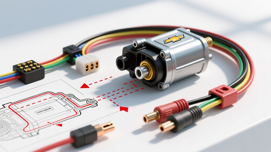
The High Cost of Starter Wiring Errors on the Chevy S10
The Chevrolet S10 is a legendary compact truck, but its electrical system—particularly the starter circuit—is notoriously unforgiving of sloppy repairs. When consulting a standard chevy s10 starter wiring diagram, most DIYers focus solely on connecting the main battery cable to the solenoid and calling it a day. However, the S10 starter circuit involves a complex interplay between the ignition switch, the Powertrain Control Module (PCM), the neutral safety switch (NSS), and the clutch interlock system. Misinterpreting these schematics leads to melted harnesses, backfed PCM modules, and dangerous unintended cranking.
This guide bypasses the basic plug-and-play advice and dives deep into the common mistakes, critical safety warnings, and exact OEM specifications required to wire or repair the starter circuit on the GMT325 and GMT330 generation S10s (1994–2004), specifically focusing on the 2.2L I4 and 4.3L Vortec V6 platforms.
Anatomy of the Chevy S10 Starter Circuit
Before turning a wrench, you must understand the distinct pathways of the S10 starter system. Unlike older carbureted trucks that utilized a ballast resistor bypass, the 1994+ Vortec S10s rely on the PCM to manage fuel and spark mapping during crank. The starter solenoid typically features a large threaded B+ stud and a small spade terminal (the 'S' terminal). Some aftermarket or remanufactured starters may include an 'R' or 'I' terminal, which is a frequent source of wiring disasters on fuel-injected S10s.
OEM Wire Color Codes & AWG Specifications
| Circuit Function | OEM Wire Color | AWG Size | Solenoid Terminal | Destination / Notes |
|---|---|---|---|---|
| Main Power (B+) | Red | 2 AWG or 4 AWG | Large Threaded Stud | Battery Positive / Alternator B+ |
| Crank Signal | Purple | 12 AWG | 'S' (Small Spade) | Ignition Switch via NSS/Clutch Interlock |
| PCM Crank Reference | Yellow/Black | 18 AWG | PCM Harness | VCM/PCM Pinout (Signals engine cranking) |
| Engine Ground | Braided Copper | 4 AWG or 6 AWG | Block Bolt | Chassis Rail / Battery Negative |
5 Critical Wiring Mistakes That Fry S10 Harnesses
Mistake 1: The 'R' Terminal Backfeed Disaster
Many remanufactured starters come with an 'R' (Resistor bypass) terminal. On pre-1990 points-style ignitions, this terminal sent 12V to the coil during cranking. On a 1994+ Vortec S10, connecting a constant 12V source or miswiring the 'R' terminal can backfeed voltage directly into the PCM's ignition control module circuits. This will instantly blow the IGN fuse and can permanently fry the PCM. The Fix: Leave the 'R' terminal completely empty and capped on all 1994-2004 fuel-injected S10 models.
Mistake 2: Bypassing the Clutch Interlock or Neutral Safety Switch
To diagnose a no-crank condition, many mechanics jump the starter solenoid directly or wire a push-button switch in the cab, entirely bypassing the clutch pedal position switch (manual transmission) or the Park/Neutral Position switch (automatic). This defeats a critical safety mechanism. If the truck is left in gear and the interlock is bypassed, engaging the starter will cause the vehicle to violently lurch forward, posing a severe crush hazard to anyone standing in front of the bumper. Always route the 12 AWG purple crank wire through the factory safety interlock relays.
Mistake 3: Routing the Purple Crank Wire Near the Exhaust
On the 4.3L Vortec V6, the passenger-side exhaust manifold sits dangerously close to the starter solenoid. A common error is routing the purple 'S' terminal wire over the top of the solenoid where it rests against the hot cast-iron manifold. The insulation melts, the bare copper shorts against the manifold, and the ignition fuse blows every time the key is turned. Route the purple wire downward, wrapping it in high-temp fiberglass sleeving, and secure it with stainless steel zip ties away from exhaust components.
Mistake 4: Undersizing the B+ Battery Cable
The S10 starter requires massive cold cranking amps (CCA), often exceeding 500 amps at peak load. Using 6 AWG or 8 AWG wire for the main B+ battery cable creates severe voltage drop. According to SAE J1128 standards for low-tension primary cable, undersized wiring will overheat, melt the insulation, and starve the starter of the voltage required to engage the Bendix drive. Always use a minimum of 4 AWG stranded copper for runs under 6 feet, and upgrade to 2 AWG if running a high-torque aftermarket mini-starter.
Mistake 5: Ignoring the Engine Block Ground Strap
The starter grounds through the engine block, not through a dedicated wire on the starter casing. If the heavy braided ground strap connecting the engine block to the chassis rail is corroded or missing, the starter will seek a ground path through the path of least resistance. This usually means sending 400+ amps through the steel throttle cable, the heater core hoses, or the transmission shift linkage, melting them instantly. Always verify the block-to-chassis ground strap is clean, tight, and free of paint or oil.
Safety Warnings & Pre-Work Protocols
- Disconnect the Battery: Never work on the starter B+ terminal with the battery connected. The main cable is unfused and directly tied to the battery positive post. A dropped wrench here will weld to the metal, cause a battery explosion, or start an electrical fire.
- Torque Specifications: The M8 or M10 threaded stud on the starter solenoid is fragile. Overtightening the B+ cable nut will snap the stud, ruining the solenoid. Use a torque wrench set to 12 Nm (9 lb-ft) for M8 studs and 15 Nm (11 lb-ft) for M10 studs.
- Use Adhesive-Lined Heat Shrink: Never use standard vinyl electrical tape to seal starter connections. The under-hood heat and vibration will cause the tape to unravel, inviting moisture and corrosion. Use 3M adhesive-lined marine-grade heat shrink tubing to seal all ring terminals.
Step-by-Step Diagnostic Decision Tree
Use this logical flow to diagnose S10 starter wiring faults without throwing unnecessary parts at the truck.
- Symptom: Single loud 'Click' from the starter, but engine does not turn over.
- Cause: High resistance on the B+ cable, poor engine ground, or a seized starter motor.
- Fix: Perform a voltage drop test. Place multimeter probes on the battery positive post and the starter B+ stud while an assistant cranks. A reading above 0.5V indicates a failing cable or corroded terminal.
- Symptom: Rapid, machine-gun clicking from the solenoid.
- Cause: The battery is severely depleted, or the purple 'S' wire is receiving fluctuating voltage due to a failing ignition switch or corroded clutch interlock switch.
- Fix: Check battery voltage under load. If battery is healthy, probe the purple 'S' wire at the solenoid during crank. It must maintain a steady 10.5V+.
- Symptom: Starter spins (whirring sound) but does not engage the flexplate.
- Cause: Internal solenoid failure, or the Bendix drive is jammed with debris/rust.
- Fix: Replace the starter assembly. Ensure the flexplate teeth are inspected for shearing.
- Symptom: Truck cranks perfectly, but will not start (No spark/no fuel).
- Cause: The PCM is not receiving the crank reference signal because the Yellow/Black wire was damaged or the 'R' terminal was miswired, confusing the VCM.
- Fix: Scan for PCM communication. Verify wiring at the PCM connectors and ensure the 'R' terminal on the starter is vacant.
Authoritative References
For further technical validation, refer to the following automotive electrical resources:
- SAE International - J1128: Low Tension Primary Cable Standards (Defines AWG requirements and insulation heat ratings for automotive starter circuits).
- GM Heritage Center - Service Information Archives (OEM wiring schematics and PCM pinout data for GMT325/330 platforms).
- Painless Performance Products - Technical Wiring Guides (Best practices for high-amperage routing, terminal crimping, and heat shrink application).