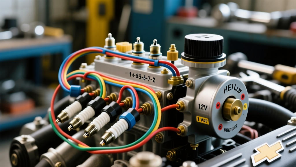
The 'Spark Plug Wiring Diagram' Myth: HEI vs. Plug Wire Routing
When enthusiasts and mechanics search for a spark plug wiring diagram Chevy 350, they are often chasing a phantom. Spark plugs are passive, high-voltage discharge components; they do not possess multi-pin wiring harnesses or ECU-level schematics. Instead, what is actually required to properly 'wire' a Chevy 350 Small Block (Gen I or Vortec) ignition system are two distinct technical references: the High Energy Ignition (HEI) distributor power feed circuit and the physical spark plug wire routing diagram (firing order and inductive separation).
Misunderstanding the difference between these two systems is the leading cause of weak spark, burnt ignition modules, and catastrophic carburetor backfires. This guide breaks down the critical safety warnings, OEM wire color codes, and the most common wiring mistakes made when servicing the Chevy 350 ignition system.
Critical High-Voltage Safety Warnings
Before touching any ignition wiring on a Chevy 350, you must respect the voltage parameters of the system. The GM HEI distributor generates between 35,000 and 45,000 volts under load. Unlike older points-style systems, this voltage is lethal and can cause severe capacitive discharge injuries or induce cardiac events in individuals with pacemakers.
- Battery Disconnect Protocol: Always disconnect the negative battery terminal before routing plug wires or testing the HEI cap. A crank signal can fire the coil unexpectedly.
- Capacitive Bleed-Down: The HEI ignition coil stores high-voltage energy. After shutting off the engine, ground the primary coil wire to the engine block for 5 seconds before removing the distributor cap to bleed residual capacitance.
- ECM/PCM Protection (Late Model 350s):strong> If you are working on a 1996-2000 Vortec 5.7L (L31) or a late-80s TBI 350, the HEI module is tied to the PCM via the Electronic Spark Timing (EST) circuit. Disconnecting the 4-pin EST connector while the key is ON can fry the PCM driver. Always key-off before unplugging the 4-pin weatherpack connector.
Top 4 Chevy 350 Ignition Wiring Mistakes (And How to Fix Them)
Mistake 1: Feeding HEI with a Ballast Resistor Wire
The most destructive mistake made during a Chevy 350 HEI swap or repair is using the factory points-era resistance wire to power the distributor. Pre-1974 GM vehicles used a resistance wire (often a cloth-braided Pink wire or a specific White/Red tracer) that dropped the 12V system down to 7V-9V to protect the breaker points.
The Failure Mode: The HEI module requires a full, uninterrupted 12V to 14V during both CRANK and RUN. If fed with resistance wire, the spark output drops drastically under load, and the internal HEI module will overheat and fail prematurely due to amperage starvation.
The Fix: Run a new dedicated 12 AWG stranded copper wire from a switched 12V ignition fuse in the fuse box directly to the HEI 'BAT' terminal. Use a 30A automotive relay triggered by the ignition switch if the factory fuse block cannot handle the 5-amp draw of the HEI module.
Mistake 2: Inductive Crossfire on Cylinders 5 & 7
The Chevy 350 firing order is 1-8-4-3-6-5-7-2. Cylinders 5 and 7 fire sequentially in the cycle. On the passenger side valve cover, the spark plug wires for cylinders 5 and 7 must be routed from the distributor cap to the rear of the engine.
The Failure Mode: If wires 5 and 7 are routed parallel to each other and zip-tied together, the massive electromagnetic field generated by cylinder 7's firing pulse will induce a premature, ghost voltage in cylinder 5's wire. This is called inductive crossfire. It causes cylinder 5 to fire while the intake valve is open, resulting in a violent backfire through the carburetor that can shatter the air horn or start an engine bay fire.
The Fix: Never route sequential firing order wires parallel. Use a wire loom separator to cross wire 5 over wire 7 at a 90-degree angle, or stagger them using factory-style aluminum wire looms with individual channels. For high-performance builds, upgrade to 8.5mm spiral-core silicone wires which resist magnetic interference better than standard 7mm carbon-core wires.
Mistake 3: Incorrect Rotor Phasing and Cap Alignment
Many mechanics use a 'spark plug wiring diagram' to match the cap terminals to the cylinders but fail to verify rotor phasing. The Chevy 350 distributor rotates clockwise. The terminal marked '1' on the HEI cap must align with the rotor tip when cylinder 1 is at Top Dead Center (TDC) on the compression stroke.
The Failure Mode: If the cap is installed 180 degrees out of phase, or if the oil pump drive shaft was dropped in incorrectly (causing the distributor to seat one tooth off), the rotor will be pointing at the edge of the terminal rather than dead center. This causes 'cross-arc' inside the cap, burning the brass contacts and causing high-RPM misfires.
Mistake 4: Dielectric Grease Misapplication
Dielectric grease is an insulator, not a conductor. A common error is packing the inside of the spark plug boot terminal with grease, assuming it helps electricity flow.
The Failure Mode: Grease inside the terminal creates a barrier that increases resistance, leading to heat buildup, arcing, and melted boots.
The Fix: Apply a thin ring of dielectric grease only to the outside of the spark plug ceramic insulator and the inner lip of the rubber boot. This seals out moisture and prevents the boot from bonding to the ceramic, without interfering with the metal-to-metal terminal connection.
Chevy 350 HEI Wiring & Firing Order Specification Table
| Specification | OEM / Technical Requirement | Notes / Tolerances |
|---|---|---|
| Firing Order | 1-8-4-3-6-5-7-2 | Standard for all Gen I and Vortec 90-degree V8s |
| Distributor Rotation | Clockwise | Viewed from above the cap |
| HEI Power Feed Wire | 12 AWG Stranded Copper | Must carry full 12V-14V (No ballast resistor) |
| HEI Cap 'BAT' Terminal | 12V Switched Ignition | Fused at 10A to 15A maximum |
| HEI Cap 'TACH' Terminal | Signal to Tachometer | Do not ground this terminal; will destroy module |
| Spark Plug Gap (Gen I) | 0.045 inches | Standard for non-emissions, pre-catalyst setups |
| Spark Plug Gap (Vortec L31) | 0.060 inches | Required for lean-burn efficiency and COP-style energy |
| Plug Torque (Cast Iron Heads) | 15 - 20 lb-ft | Use anti-seize on threads; reduce torque by 10% |
| Plug Torque (Aluminum Heads) | 11 - 15 lb-ft | Critical to prevent thread stripping in aluminum |
Step-by-Step: Upgrading the HEI Power Feed Circuit
If your Chevy 350 is experiencing high-RPM misfires or the HEI module keeps burning out, follow this relay-based wiring upgrade. This ensures the coil receives maximum voltage directly from the battery, bypassing aging factory wiring.
- Mount a 30A Bosch-style relay on the firewall or inner fender, away from exhaust headers.
- Pin 30 (Power In): Run a 10 AWG red wire directly from the positive battery terminal, protected by a 15A inline maxi-fuse.
- Pin 86 (Switched Trigger): Connect to the factory ignition-switched 12V source (the old resistance wire is fine here, as it only triggers the relay coil, which draws less than 1 amp).
- Pin 85 (Ground): Ground to a clean, bare metal point on the engine block or intake manifold using a ring terminal and star washer.
- Pin 87 (Output): Run a 12 AWG pink or red wire directly to the 'BAT' terminal on the HEI distributor cap.
This configuration guarantees that the HEI module sees battery voltage minus only the negligible resistance of a short, heavy-gauge wire, eliminating voltage drop across the firewall bulkhead connector.
Expert Troubleshooting: Symptom-to-Cause Decision Tree
- Symptom: Engine backfires through carburetor at 2,500+ RPM.
Cause: Inductive crossfire (wires 5 & 7 parallel) or worn cap/carbon tracking.
Fix: Reroute wires with separators; inspect cap interior for white/lightning-burn marks. - Symptom: Engine dies when hot, restarts when cold.
Cause: HEI module thermal failure due to undersized power wire or missing thermal paste.
Fix: Verify 12V at BAT terminal under load. Apply dielectric thermal compound between module and distributor housing. - Symptom: Tachometer reads erratically or pegs to max.
Cause: TACH terminal shorted to ground or failing coil diode.
Fix: Check wiring to tachometer; ensure TACH terminal is not touching the shield.
Authoritative References & Further Reading
For deeper diagnostics on GM ignition systems, always refer to OEM service data and established ignition manufacturers. The following resources provide foundational data on HEI module pinouts and inductive wire routing physics:
- MSD Ignition Technical Support & Wiring Guides - Detailed breakdowns of HEI cap phasing, magnetic interference, and coil saturation times.
- Summit Racing Tech: Firing Order and Wire Routing - Visual diagrams for small block Chevy wire loom configurations to prevent crossfire.
- SAE International Technical Papers - Search for 'Inductive Crossfire in High Voltage Ignition Systems' for the electrical engineering principles behind spark plug wire separation.