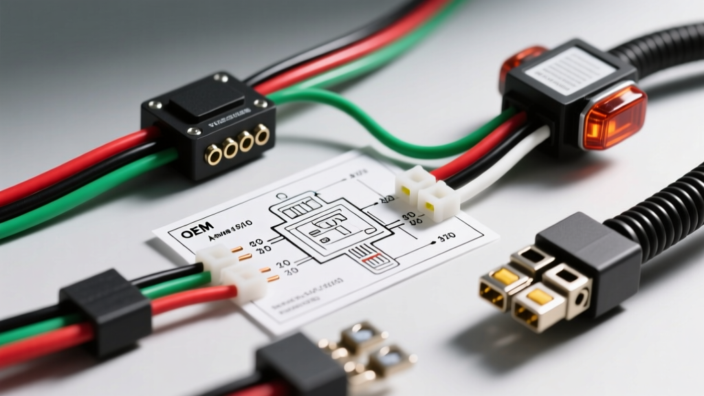
Decoding the Wiring Diagram for Reverse Lights
When troubleshooting, repairing, or modifying automotive lighting, understanding the complete wiring diagram for reverse lights is critical for both safety and legal compliance. Unlike parking lights or headlights, which are driver-initiated via a stalk switch, the reverse light circuit is mechanically or electronically interlocked with the vehicle's transmission state. This ensures the illumination of the rear backup lamps—and the corresponding activation of trailer reverse circuits and rear-view camera systems—occurs exclusively when the transmission is placed in the REVERSE gear.
From a regulatory standpoint, backup lamps are strictly governed by Federal Motor Vehicle Safety Standard (FMVSS) 108. This standard mandates that reverse lights must emit white light, meet specific candela requirements for photometric output, and remain inactive in all forward gears. Furthermore, the physical wiring and insulation must adhere to SAE J1128 standards for low-tension primary cable, ensuring the harness can withstand underhood and underbody thermal cycling without degrading.
Evolution of the Reverse Light Circuit Architecture
Before diving into the schematic walkthrough, it is vital to identify which generation of electrical architecture your vehicle utilizes. The wiring diagram for reverse lights generally falls into one of two categories:
- Discrete Hardwired Systems (Pre-2010 mostly): Power flows from a fuse, through a mechanical Transmission Range Sensor (TRS) or neutral safety switch, and directly to the rear lamp sockets via a continuous copper trace. This is the most common setup in classic trucks, older passenger cars, and heavy-duty commercial vehicles.
- Multiplexed / BCM-Controlled Systems (Modern): The transmission control module (TCM) or Powertrain Control Module (PCM) reads the gear selector position via a CAN-bus network. It then sends a digital message to the Body Control Module (BCM), which uses an internal solid-state driver to output 12V to the reverse lights. These diagrams feature communication buses rather than continuous power wires.
Anatomy of a Discrete Hardwired Reverse Light Circuit
For this walkthrough, we will trace a classic discrete hardwired system, typical of the highly prevalent GM GMT800 platform (Silverado/Sierra) and similar Ford F-Series architectures. This represents the foundational logic for 80% of aftermarket trailer wiring and basic automotive electrical repairs.
1. Power Source and Overcurrent Protection
The circuit originates at the underhood fuse block or the interior instrument panel fuse block. It is protected by a dedicated 15A or 20A blade fuse (commonly labeled 'B/U LP', 'BACKUP', or 'REV'). The fuse is fed by an ignition-switched or battery-hot bus bar, depending on whether the OEM requires the key to be in the 'ON' or 'RUN' position for the lights to function. The wire leaving the fuse is typically 18 AWG (sometimes 16 AWG for long-wheelbase vehicles to mitigate voltage drop) and is routed through the firewall grommet into the engine bay.
2. The Transmission Range Sensor (TRS) / Reverse Switch
In automatic transmissions, the power wire terminates at the Transmission Range Sensor (also known as the PRNDL switch), mounted externally on the transmission housing. The TRS contains a rotating wiper that bridges specific internal contacts based on the shifter shaft's position. When shifted into Reverse, the wiper connects the 12V input terminal to the reverse light output terminal. In manual transmissions, this is handled by a simple normally-open (NO) mechanical plunger switch threaded into the transmission case, which closes the circuit when the reverse shift rail engages.
3. Rear Harness Routing and Trailer Tow Integration
The output wire from the TRS runs down the vehicle's main chassis harness to the rear junction block or trailer tow module. In vehicles equipped with a factory tow package, this wire acts as the 'trigger' or 'feed' for the reverse lockout solenoid on the trailer connector (usually the center pin of a 7-way RV blade connector). The harness then splits at the rear bumper or tailgate jamb, sending 18 AWG leads to the left and right tail light assemblies.
OEM Wiring Specifications and Color Codes
While wire colors can vary by manufacturer and model year, the following table represents standard OEM color codes and specifications for typical North American domestic trucks and SUVs.
| Circuit Segment | GM OEM Color | Ford OEM Color | AWG Size | Connector Type |
|---|---|---|---|---|
| Fuse to TRS / Switch | Pink | Red / Yellow | 18 AWG | Metri-Pack 280 |
| TRS to Rear Junction | Light Green | Black / Pink Stripe | 18 AWG | Weather-Pack / Splice |
| Junction to Lamp Socket | Light Green | Black / Pink Stripe | 18 AWG | Socket Pigtail |
| Lamp Socket Ground | Black | Black | 18 AWG | Ring Terminal (M6) |
Note: Always verify with a vehicle-specific service manual, as SAE J1122 lighting standards dictate performance, not specific insulation colors.
Multiplexed and BCM-Controlled Systems
If your wiring diagram for reverse lights shows a module with thin, twisted-pair wires (CAN-High and CAN-Low) instead of thick power wires, you are dealing with a multiplexed system. In these vehicles, the TRS sends a digital gear-position message over the High-Speed CAN bus (typically 500 kbps) to the BCM. The BCM then activates an internal High-Side Driver (HSD).
Modern BCMs utilize Pulse Width Modulation (PWM) and current-sensing shunts to monitor the reverse light circuit. If a bulb burns out, the BCM detects the drop in current draw and illuminates a 'Check Reverse Lamp' message on the driver information center. Furthermore, these solid-state drivers feature thermal fold-back protection; if a short to ground occurs in the rear harness, the BCM will cut power in milliseconds to prevent wiring harness fires, resetting only after the ignition is cycled.
Step-by-Step Schematic Walkthrough & Diagnostics
When reading the schematic, follow this logical diagnostic sequence to isolate faults without unnecessarily stripping the interior trim or dropping the transmission pan.
- Verify the Fuse: Use a test light or digital multimeter (DMM) to check for 12V on both sides of the B/U LP fuse with the ignition ON. If power is missing on the load side, replace the fuse. If it blows immediately, you have a short to ground between the fuse block and the TRS.
- Test the Switch Input: Locate the TRS connector on the transmission. Back-probe the input wire (e.g., Pink). You should have battery voltage. If not, repair the open circuit between the fuse block and the transmission.
- Test the Switch Output: With the vehicle safely elevated and wheels chocked, shift into REVERSE. Back-probe the output wire (e.g., Light Green). If you have 12V here, the switch is functioning. If you have 0V, the TRS is either internally failed or mechanically misaligned on the shift shaft.
- Check the Rear Junction / Split: Locate the rear body harness connector (often under the driver's side rear bed rail or inside the rear quarter panel). Probe the reverse light pin. If voltage is present here but the bulbs do not illuminate, the fault is isolated to the rear lamp pigtails or grounds.
- Perform a Voltage Drop Test on the Ground: A common failure mode is a corroded chassis ground (e.g., G401 or G403). Set your DMM to DC Volts. Place the red probe on the battery positive terminal and the black probe on the black ground wire at the tail light socket (with the circuit active). A reading above 0.2V indicates excessive resistance in the ground path. Clean the M6 ground bolt and chassis contact point with a wire brush, apply dielectric grease, and torque to 9 Nm (80 lb-in).
Common Failure Modes and Real-World Insights
Beyond simple bulb burnout, the most frequent issue encountered when tracing a wiring diagram for reverse lights is TRS misalignment. If the shift linkage stretches or the transmission mount sags, the physical position of the shifter may no longer align perfectly with the internal wiper of the TRS. The symptom is often a vehicle that starts fine in Park but the reverse lights flicker or fail to engage until the shifter is jiggled slightly. The fix involves loosening the TRS mounting bolts, aligning the neutral timing marks on the switch housing, and retightening to OEM torque specifications.
Another prevalent issue is trailer wiring feedback. In vehicles with aftermarket 4-flat or 7-way adapters spliced into the rear harness, moisture ingress into the trailer connector can cause a short between the 12V auxiliary pin and the reverse light pin. This back-feeds voltage into the BCM or fuse block, often resulting in blown fuses or erratic behavior of the rear-view camera system. Always inspect trailer connectors for green copper oxide corrosion and use dielectric grease on all exposed terminals.
By systematically following the wiring diagram from the power source, through the switching mechanism, and down to the load and ground, you can accurately diagnose and repair any reverse light circuit, ensuring your vehicle remains safe, compliant, and ready for the road.