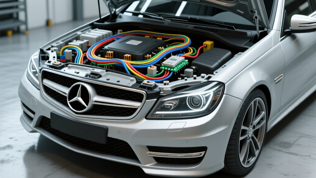
Understanding the W204 Lighting Architecture
When diagnosing exterior lighting faults on the 2008-2014 C-Class, consulting a standard W204 Mercedes Benz headlight wiring diagram reveals a highly networked architecture. Unlike older vehicles where the headlight switch directly routes 12V power through a relay to the bulbs, the W204 utilizes a multiplexed CAN bus system. The physical headlight switch acts merely as a sensor input to the Steering Column Module (SCM/MRM). The SCM then transmits a CAN B network message to the Front Signal Acquisition Module (SAM F, designated as N10/1 in Mercedes-Benz schematics). The SAM F contains internal solid-state semiconductor drivers—rather than traditional mechanical relays—to supply pulse-width modulated (PWM) or steady 12V DC power to the headlight assemblies.
Because the SAM F monitors current draw on every lighting circuit to detect bulb outages, introducing incorrect wattage bulbs, LED conversions without CAN-bus decoders, or experiencing high-resistance ground faults will cause the SAM F to shut down the circuit entirely to protect its internal silicon. This troubleshooting flow is designed to systematically isolate failures between the bulb, the wiring harness, the SAM F, and the network communication layer.
W204 Mercedes Benz Headlight Wiring Diagram: Front SAM Pinouts
The Front SAM (N10/1) is located in the driver-side engine compartment fuse box. For standard Halogen-equipped W204 models, the low and high beam circuits originate from the X4 and X5 multi-pin connectors on the SAM F. Below is the reference specification chart for the primary headlight power feeds. Note that Mercedes-Benz wire colors utilize a two-tone code (e.g., Gr/Wh = Green with White tracer).
| Circuit Function | SAM F Connector | Pin Number | OEM Wire Color | AWG Size | Destination |
|---|---|---|---|---|---|
| Left Low Beam (H7) | X4 | 12 | Green/White (Gr/Wh) | 18 AWG | Left Headlamp Assy (E1) |
| Right Low Beam (H7) | X4 | 14 | Blue/Red (Bl/Rd) | 18 AWG | Right Headlamp Assy (E2) |
| Left High Beam (H7) | X5 | 8 | Green/Yellow (Gr/Ye) | 18 AWG | Left Headlamp Assy (E1) |
| Right High Beam (H7) | X5 | 10 | Blue/Black (Bl/Bk) | 18 AWG | Right Headlamp Assy (E2) |
| Common Ground (Chassis) | N/A | N/A | Brown (Br) | 16 AWG | Ground Points Z18/12 & Z18/13 |
Step-by-Step Headlight Troubleshooting Flow
Follow this diagnostic decision tree to isolate the root cause of W204 headlight failures. Ensure you have a digital multimeter (DMM), a set of back-probes, and ideally a bi-directional OBD2 scanner capable of reading Mercedes-specific SAM modules.
Phase 1: Visual & Physical Inspection (The Melted Connector Plague)
Symptom: One low beam is inoperative. Dash displays 'Low Beam Left/Right' warning. High beams function normally. Step 1.1: Remove the rear access cap on the affected headlight housing. Extract the H7 bulb and inspect the PX26d plastic connector base. Step 1.2: Look for thermal deformation, brown scorch marks, or melted plastic around the ground pin tab. The OEM H7 halogen bulbs draw approximately 55W (4.5 Amps). Over years of thermal cycling, micro-arcing at the terminal increases electrical resistance. This resistance generates excessive heat, melting the plastic housing and causing an open circuit. Step 1.3 (The Fix): If the connector is melted, do not simply replace the bulb. You must cut off the damaged OEM pigtail and splice in a high-temperature ceramic H7 connector pigtail. Use 14 AWG stranded copper wire and adhesive-lined marine heat shrink to ensure a moisture-tight, low-resistance seal. Upgrading to ceramic prevents repeat failures.
Phase 2: Voltage Drop & Ground Circuit Testing
Symptom: Bulb and connector are pristine, but the bulb does not illuminate, or it glows dimly. Step 2.1: Set your DMM to DC Volts. Back-probe the power wire (e.g., Gr/Wh for Left Low Beam) at the bulb connector with the headlights commanded ON. Step 2.2: Measure voltage between the power pin and the battery negative terminal. If you read 12.5V, the SAM F is outputting power correctly. Step 2.3: Perform a voltage drop test on the ground side. Place the positive DMM lead on the battery negative terminal and the negative DMM lead on the Brown (Br) ground wire at the bulb connector. With the circuit loaded (bulb connected and attempting to draw current), a healthy ground will show a voltage drop of less than 0.1V. If you read 0.5V or higher, you have high resistance at Ground Point Z18/12 (Left) or Z18/13 (Right). Step 2.4 (The Fix): Locate the ground stud behind the headlamp assembly near the inner fender liner. Remove the M6 nut (torque spec: 8 Nm upon reassembly), clean the ring terminal and chassis contact patch with a wire brush, apply dielectric grease to the surrounding area (not the contact patch), and re-secure.
Phase 3: Front SAM (Signal Acquisition Module) Diagnostics
Symptom: Zero volts at the headlight connector. Ground circuit tests perfectly. Fuses in the SAM F are intact. Step 3.1: The W204 SAM F does not use traditional replaceable blade fuses for the low beam circuits; it uses internal solid-state drivers protected by internal resettable fuses. However, check the main SAM power supply fuses (typically large 30A/40A J-case fuses in the pre-fuse box near the battery) to ensure the SAM has primary B+ power. Step 3.2: Connect a bi-directional scan tool (e.g., XENTRY, Autel MaxiSys, or Snap-on Zeus). Navigate to Control Units -> SAM F -> Activations. Command the 'Left Low Beam' ON. Step 3.3: If the scan tool commands the light ON, but the physical headlight switch does not, your fault lies in the Steering Column Module (SCM) or the CAN B network wiring between the SCM and SAM. Step 3.4: If the scan tool commands the light ON, but voltage remains at 0V at the bulb harness, the internal solid-state driver inside the SAM F has failed. Step 3.5 (Water Ingress Check): Before condemning the SAM F, inspect the module for water damage. The W204 is notorious for clogged sunroof drains and deteriorating hood-to-cowl rubber seals. Water pools in the driver-side cowl and drains directly into the SAM F enclosure. Look for white/green crusty corrosion on the X4/X5 connector pins. If corrosion is present, the SAM F must be replaced and SCN coded to the vehicle's VIN using XENTRY.
Bi-Xenon vs. Halogen: Wiring Divergences
If your W204 is equipped with the optional Bi-Xenon package (Code 622), the wiring diagram changes significantly. The H7 halogen bulbs are replaced by D1S Xenon bulbs. The SAM F no longer sends a direct 12V feed to the bulb itself. Instead, the SAM F sends a 12V power feed (14 AWG) to the Xenon Ballast (N71/1 or N71/2), which is mounted beneath the headlight assembly.
The SAM F then communicates with the ballast via a dedicated LIN (Local Interconnect Network) bus wire. The ballast contains the internal igniter circuitry required to generate the 25,000V strike voltage for the D1S capsule. Troubleshooting Bi-Xenon systems requires swapping the ballast from the working side to the non-working side to isolate whether the fault lies in the ballast, the D1S capsule, or the SAM F LIN-bus signal wire.
Authoritative References & Further Reading
- For official OEM wiring schematics, component locations, and torque specifications, technicians should consult the Mercedes-Benz StarTekInfo Workshop Information System (WIS), which requires a subscription but provides factory-level accuracy.
- For standardized testing procedures regarding automotive lighting circuits, voltage drop limits, and PWM diagnostics, refer to the SAE International automotive electrical testing guidelines and surface vehicle recommended practices.
- Real-world case studies on W204 SAM F water ingress and H7 connector melting can be cross-referenced through the International Automotive Technicians Network (iATN) fix databases and technical service bulletins.