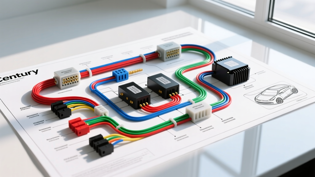
Mastering the EV Conversion: Century 3-Phase AC Induction Motors
When executing a custom electric vehicle (EV) conversion, selecting the right propulsion motor is only half the battle; the electrical integration dictates the reliability and drivability of the build. The wiring diagram for Century electric motor applications in EV swaps typically revolves around their robust NEMA 184T and 213T frame 3-phase AC induction motors. Originally designed for heavy-duty industrial and HVAC applications, these motors are favored by automotive fabricators for their high torque density, durability, and availability. However, adapting a fixed-frequency industrial motor to a variable-frequency EV inverter (motor controller) requires a precise understanding of terminal configurations, high-voltage (HV) DC bus management, and encoder feedback loops.
This comprehensive walkthrough provides automotive electricians and EV builders with the exact schematics, AWG sizing, and pinout configurations required to safely integrate a Century 3-phase motor with a modern EV inverter, such as a Sevcon Gen4 or Curtis 1238 series controller.
Understanding the Century 9-Lead Terminal Block
Unlike standard automotive 3-phase alternators, industrial Century motors feature a 9-lead (T1 through T9) terminal block. This dual-voltage design allows the motor to be configured in either a Wye (Star) or Delta topology, which is critical when matching the motor's impedance to your EV inverter's maximum AC voltage output.
Low-Voltage Delta Configuration (For 144V - 200V DC Bus Systems)
If your EV battery pack and inverter operate on a nominal 144V to 200V DC bus, the inverter will output a maximum line-to-line AC voltage of roughly 100V to 140V. You must wire the Century motor in the Delta configuration to prevent severe torque loss and overcurrent faults.
- Phase U (Inverter Output A): Bridge T1, T6, and T7 together.
- Phase V (Inverter Output B): Bridge T2, T4, and T8 together.
- Phase W (Inverter Output C): Bridge T3, T5, and T9 together.
High-Voltage Wye Configuration (For 300V+ DC Bus Systems)
For high-voltage EV architectures (e.g., 300V to 400V nominal DC bus derived from Tesla or Nissan Leaf battery modules), the inverter outputs higher AC voltage. Wire the motor in the Wye configuration.
- Neutral Point: Bridge T4, T5, and T6 together and insulate with heat-shrink tubing.
- Phase U: Connect Inverter Output A to T1.
- Phase V: Connect Inverter Output B to T2.
- Phase W: Connect Inverter Output C to T3.
High-Voltage DC & Precharge Circuit Walkthrough
Before 3-phase AC ever reaches the Century motor, the HV DC bus must be managed safely. Inverters contain large DC-link capacitors. If the main contactor closes without a precharge circuit, the inrush current will weld the contactor contacts and potentially destroy the inverter's IGBTs.
Precharge Logic Schematic
- Battery Positive (+) routes to the Main Contactor (e.g., Gigavac GX14 or Albright SW200) input terminal.
- Precharge Relay & Resistor: A 12V automotive relay switches a 1000-ohm, 250W wire-wound resistor in parallel with the main contactor.
- Sequence: Turning the ignition key to 'ON' triggers the precharge relay. Current flows through the resistor, slowly charging the inverter capacitors. Once the bus voltage reaches 90% of the pack voltage (measured by the inverter's internal voltage sensor), the inverter closes the main contactor and opens the precharge relay.
- HVIL (High Voltage Interlock Loop): A 12V low-current loop runs through all HV connector housings, the emergency disconnect, and the inverter lid. If any HV cover is removed, the HVIL breaks, instantly dropping the main contactor.
3-Phase AC Cable Sizing & Torque Specifications
Automotive environments subject wiring to severe vibration and thermal cycling. The cables connecting the inverter to the Century motor must be flexible, high-strand-count EV cable (e.g., XLPE insulated), not solid-core building wire.
| Circuit Segment | Peak Current | Recommended AWG | Terminal Torque Spec | Insulation Type |
|---|---|---|---|---|
| Battery to Inverter (HV DC) | 400A - 600A | 2/0 AWG | 12 - 15 ft-lbs | XLPE (Orange) |
| Inverter to Century Motor (U, V, W) | 300A - 450A | 1/0 AWG or 2 AWG | 45 in-lbs (NEMA block) | XLPE (Orange) |
| Precharge Resistor Leads | 5A - 10A | 14 AWG | Snug + Loctite | High-Temp Silicone |
| Contactor Coil / 12V Logic | 2A - 5A | 16 AWG | N/A (Spade/Boot) | TXL / GXL |
Encoder Retrofit and Pinout Configuration
Century NEMA-frame motors do not ship with the incremental encoders required for Field Oriented Control (FOC) by modern EV inverters. Builders must machine an adapter bell-housing and mount a 3-channel incremental encoder (e.g., USDigital or Encoder Products Company) to the rear shaft. Standard resolution for EV traction applications is 1024 PPR (Pulses Per Revolution).
Standard 5V Incremental Encoder Pinout
Use Belden 9841 or equivalent twisted-pair shielded cable for encoder wiring. Electromagnetic interference (EMI) from the 3-phase AC cables will induce false counts in unshielded wires, causing the inverter to miscalculate rotor position and trigger violent overcurrent shutdowns.
| Encoder Pin | Signal | Wire Color (Typical) | Inverter Connection |
|---|---|---|---|
| 1 | Vcc (5V DC) | Red | 5V Reference Out |
| 2 | Ground | Black | Sensor GND |
| 3 | Channel A | White | Encoder A+ |
| 4 | Channel A (Not) | White/Black | Encoder A- |
| 5 | Channel B | Green | Encoder B+ |
| 6 | Channel B (Not) | Green/Black | Encoder B- |
| 7 | Channel Z (Index) | Blue | Encoder Z+ |
| 8 | Channel Z (Not) | Blue/Black | Encoder Z- |
| Shield | Drain Wire | Bare Copper | Inverter Chassis (One end only) |
Crucial Note: Only ground the encoder shield at the inverter chassis. Grounding it at both the motor and the inverter creates a ground loop, allowing HV switching noise to fry the 5V logic board.
Thermal Protection Integration
Most Century industrial motors feature embedded Klixon thermal switches or PTC thermistors buried deep within the stator windings. In an EV application, the motor is subjected to high-RMS current launches that can overheat the windings long before the outer casing feels warm to the touch.
- Normally Closed (NC) Klixons: Wire the embedded thermostat in series with the inverter's 'Motor Temp Fault' input. If the stator exceeds 135°C (275°F), the circuit opens, and the inverter immediately derates torque output to 20% to prevent insulation meltdown.
- PTC Thermistors: If your Century motor uses a 3-wire PTC network, route these to the inverter's dedicated PTC analog input pins. Do not apply 12V to a PTC circuit; it requires a precise 5V pull-up and analog-to-digital conversion.
Troubleshooting Common EV Swap Faults
Symptom: Motor Cogging or Violent Stuttering at Low RPM
- Cause: EMI noise corrupting the encoder signal, or incorrect phase sequence.
- Fix: Verify that the 3-phase AC cables (U, V, W) are routed at least 4 inches away from the low-voltage encoder cable. If swapping U and V (which reverses motor rotation) results in smoother operation, the inverter's software phase-sequence parameter was inverted relative to the physical wiring.
Symptom: Inverter Overcurrent Fault During Hard Acceleration
- Cause: Impedance mismatch due to incorrect terminal strapping (e.g., wiring a 144V system in Wye instead of Delta).
- Fix: Disconnect HV power, discharge capacitors with a 10k-ohm discharge wand, and verify the T1-T9 continuity and strap placement against the Delta configuration chart above.
Symptom: Excessive High-Frequency Whine (NVH)
- Cause: Pulse Width Modulation (PWM) switching frequency resonance with the motor laminations.
- Fix: Access the inverter tuning software and adjust the dead-time and switching frequency. Shifting the PWM frequency from 8kHz to 12kHz often moves the acoustic noise out of the human hearing range and reduces stator heating.
Authoritative References & Standards
For further engineering data on industrial motor adaptation and EV safety standards, consult the following resources:
- A.O. Smith / Century Industrial Motor Wiring Guides - Official documentation for NEMA frame terminal configurations and thermal protection specs.
- SAE International (SAE J1766 & J2344) - Recommended practices for EV high-voltage interlock loops, precharge circuits, and human safety requirements.
- Regal Rexnord Technical Bulletins - Parent company engineering data for Century motor insulation classes (Class F/H) and dielectric withstand testing.