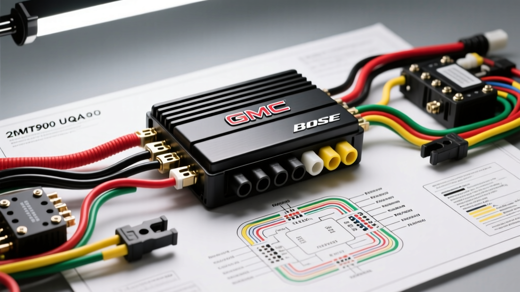
GMT900 Bose Audio Architecture Overview
The 2007 Chevrolet Tahoe marked the debut of the GMT900 platform, bringing a massive shift in automotive electrical architecture. For models equipped with the Bose Premium Audio System (RPO code UQA), the audio system is no longer a simple analog circuit. Instead, it relies on a sophisticated blend of low-level analog audio signals and multiplexed digital networks. Understanding the 2007 Tahoe Bose amp wiring diagram requires acknowledging that the amplifier acts as a network node on the vehicle's Class 2 Serial Data bus, managing audio routing, OnStar integration, and chime generation.
Located behind the passenger-side rear quarter panel trim, the UQA amplifier is housed in an aluminum heat-sink enclosure. It receives fixed-level analog audio from the head unit, processes it through an internal Digital Signal Processor (DSP) for Bose-specific equalization and surround staging, and amplifies it to drive up to nine speakers. Because the amp is deeply integrated into the vehicle's data network, diagnosing audio failures requires a dual approach: verifying high-current power delivery and analyzing digital data packets.
Amplifier Connectors and Pinout Specifications
The 2007 Tahoe Bose amplifier utilizes three primary Delphi GT 280 series connectors. These connectors feature weather-pack seals and secondary locking mechanisms to prevent vibration-induced micro-disconnects, a common issue in older GMT800 trucks. Below is the comprehensive pinout reference for the UQA amplifier.
Connector X1: Power, Ground, and Data Network
Connector X1 is the 16-pin black housing responsible for high-current power delivery and the Class 2 data handshake. Without a valid Class 2 wake-up signal and audio mute command, the amplifier will remain in a high-impedance sleep state, even if B+ voltage is present.
| Pin | Function | Wire Color | AWG | Notes |
|---|---|---|---|---|
| 1 | Battery Positive (B+) | Orange | 10 AWG | Constant 12V from underhood fuse block |
| 8 | Main Ground | Black/White | 10 AWG | Chassis ground at right rear quarter panel |
| 9 | Class 2 Serial Data | Dark Green | 18 AWG | Multiplexed network for OnStar/Chimes |
| 10 | Audio Mute Signal | Brown | 18 AWG | Active low; grounds to mute during calls |
| 16 | Ignition 1 Voltage | Pink | 18 AWG | Switched 12V reference from BCM |
Connector X2: Analog Audio Inputs (Radio to Amp)
The GMT900 Bose system uses unbalanced, low-level analog signals routed via shielded twisted pairs to minimize electromagnetic interference (EMI) from the vehicle's CAN bus and high-voltage ignition coils.
| Channel | Positive (+) Wire | Negative (-) Wire | Shielding |
|---|---|---|---|
| Left Front | Tan | Gray | Drain wire to Amp chassis |
| Right Front | Light Green | Dark Green | Drain wire to Amp chassis |
| Left Rear | Brown | Yellow | Drain wire to Amp chassis |
| Right Rear | Dark Blue | Light Blue | Drain wire to Amp chassis |
| Subwoofer | Purple | White | Coaxial shield |
Connector X3: Amplified Speaker Outputs
Outputs utilize standard GM high-level speaker wiring. The amplifier drives the front door woofers, rear door coaxials, A-pillar tweeters, and the dedicated rear cargo-area subwoofer. Ensure you maintain proper phase (polarity) when repairing these circuits, as the Bose DSP relies on phase alignment for its acoustic staging algorithms.
Wire Gauge (AWG) and Routing Specifications
When repairing or extending the wiring harness on a 2007 Tahoe, adhering to SAE J1128 standards for low-tension automotive primary wire is critical. The 10 AWG Orange B+ and Black/White Ground wires carry the bulk of the current draw, which can peak at 25-30 amps during heavy bass transients.
- Power/Ground (10 AWG): Must be crimped using closed-barrel nickel-plated terminals to prevent galvanic corrosion. Soldering is acceptable only if sealed with dual-wall adhesive-lined heat shrink.
- Audio Inputs (18-20 AWG): Must use shielded cable. If a factory shielded wire is damaged, it must be replaced with automotive-grade shielded twisted pair (STP) to prevent alternator whine from coupling into the audio signal path.
- Speaker Outputs (16 AWG): Standard GXL or TXL insulation is sufficient. Keep these wires at least 4 inches away from the Class 2 data lines to prevent inductive crosstalk.
Advanced Diagnostics: Class 2 Data and Mute Circuits
A common failure mode in the 2007 Tahoe is a completely silent audio system despite the head unit appearing to function normally. Because the radio sends analog audio continuously, the silence is almost always dictated by a failure in the digital enablement circuits. According to the SAE International J1850 Standard governing Class 2 data, the network operates at 10.4 kbps using a 0-7V square wave.
Oscilloscope Testing for Class 2 Serial Data
Do not rely solely on a multimeter to diagnose the Dark Green Class 2 wire (Pin 9, Connector X1). A digital multimeter will only show an average voltage of 2.5V to 3.5V, which is inconclusive.
- Connect your oscilloscope probe to Pin 9 and the ground clip to a known good chassis ground.
- Set the scope to DC coupling, 5V/div, and 1ms/div timebase.
- Turn the ignition to RUN. You should see a 0V to 7V square wave pulsing as the BCM, Radio, and Amp negotiate the wake-up sequence.
- If the line is pulled flat to 0V or 12V, a module on the Class 2 bus is shorting the network, preventing the amp from receiving the 'Audio Enable' message ID.
Troubleshooting the GMT900 'Speaker Pop' Syndrome
Owners frequently report a loud, singular 'pop' from the speakers when starting the vehicle or turning off the ignition. This is rarely a blown speaker. Instead, it is caused by a timing mismatch between the amplifier's internal DSP boot sequence and the decay of the analog audio signals from the head unit.
Diagnostic Decision Tree:
- Symptom: Single loud pop on key-off.
Cause: Failing electrolytic capacitors on the Bose amp DSP board failing to hold the mute circuit active during power-down.
Fix: Rebuild amplifier power supply board or replace amplifier. - Symptom: Rapid, rhythmic popping while driving.
Cause: Corroded ground at G402 (Right Rear Quarter Panel).
Fix: Remove ground bolt, sand to bare metal, apply dielectric grease, and torque to 9 Nm. - Symptom: Pop followed by complete audio loss.
Cause: Class 2 bus collision causing the amp to enter protective sleep mode.
Fix: Scan for U-codes (U1000, U1305) using a Tech 2 or GDS2 scanner to isolate the offending module.
Bypassing the UQA Amplifier for Aftermarket Integration
When upgrading the 2007 Tahoe with an aftermarket head unit and amplifier, you cannot simply splice into the Bose speaker wires. The factory head unit outputs a low-level signal tailored for the Bose DSP, and bypassing the amp requires intercepting the radio's harness before it reaches the amplifier.
Furthermore, because the Class 2 data network handles critical vehicle warnings (like the seatbelt chime and door ajar warnings) by routing them through the Bose amplifier to the left-front door speaker, removing the amp will result in the loss of these safety chimes. To retain these features, integrators must use a specialized data interface module (such as the PAC RP5-GM31 or similar GM Class 2 retention interfaces) that reads the SAE multiplexed data streams and generates the necessary analog chime signals for the aftermarket system. For comprehensive fitment and harness data, referencing the Crutchfield Vehicle Fit Database is highly recommended to ensure the correct T-harness is selected for the UQA RPO code.
Summary of Best Practices
Working on the 2007 Tahoe Bose audio system demands respect for both high-current power delivery and delicate digital data networks. Always verify B+ and Ground integrity under a simulated 20-amp load before condemning the amplifier. When probing data lines, rely on oscilloscopes rather than multimeters, and never use T-taps or scotch-locks on the Class 2 serial data or shielded audio inputs, as altering the impedance or capacitance of these circuits will lead to immediate network faults and severe audio degradation.