Mobile & Automotive Applications for Rule Pumps
While traditionally associated with marine vessels, 12V DC Rule automatic bilge pumps have become a staple in custom automotive and overland vehicle electrical systems. From heavy-duty truck bed drainage systems and amphibious vehicle modifications to mobile detailing rigs and custom auxiliary liquid-cooling reservoirs, managing water and fluids in mobile environments requires reliable, high-capacity pumping. Selecting the correct pump and executing a flawless installation requires a deep understanding of 12V DC architecture. This guide provides a comprehensive product comparison and the exact wiring diagram for Rule automatic bilge pump systems tailored for automotive and overland applications.
Model Selection Guide: Rule 500 vs. 800 vs. 1100 vs. Matrix
Before pulling wire, you must match the pump's amperage and flow rate to your vehicle's auxiliary electrical capacity. Rule offers several models, each with distinct switching mechanisms and current draws. Below is a technical comparison to help you select the right unit for your 12V mobile platform.
| Model | Capacity (GPH) | Max Amp Draw | Switch Type | Min AWG (15ft Run) | Inline Fuse |
|---|---|---|---|---|---|
| Rule 500 | 500 | 2.5A | Mechanical Float | 16 AWG | 5A |
| Rule 800 | 800 | 3.6A | Electronic Sensor | 14 AWG | 5A |
| Rule 1100 | 1100 | 5.0A | Mechanical Float | 12 AWG | 7.5A |
| Rule Matrix | 1100 / 1500 | 4.5A / 6.2A | Digital Sensing | 12 AWG | 10A |
Selection Insight: For automotive truck bed drains where debris is common, the mechanical float (Rule 500/1100) is preferred over electronic sensors, which can foul from mud or road grime. For enclosed mobile detailing tanks, the Matrix series offers superior dry-run protection.
Understanding the 3-Wire Configuration
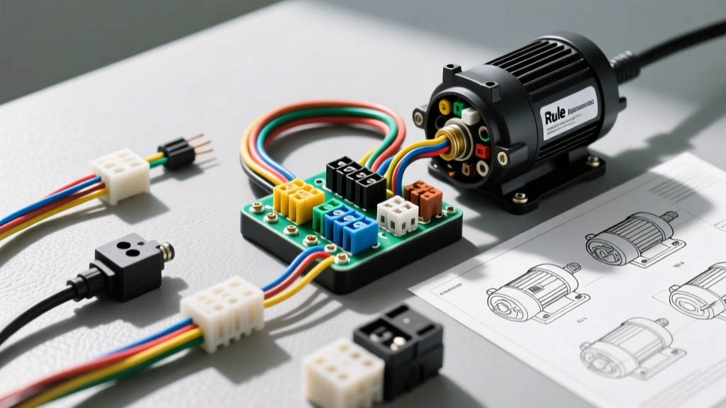
Most Rule automatic bilge pumps utilize a 3-wire harness. Understanding this color code is critical before integrating the pump into your vehicle's fuse block or auxiliary busbar.
- Black Wire: 12V DC Ground (Negative). Must be terminated to a clean, bare-metal chassis ground or a dedicated negative busbar.
- Brown Wire: 12V+ Automatic Feed. This wire connects to the internal float or electronic switch. When water rises, the switch closes, sending power from this wire to the motor.
- Brown Wire with White Stripe: 12V+ Manual Override. Bypasses the internal switch, allowing the operator to force the pump on via a dashboard toggle switch.
The Complete Wiring Diagram for Rule Automatic Bilge Pump Systems
There are two primary ways to wire these pumps in an automotive context: a direct-to-battery setup (standard for standalone drainage) and a relay-controlled setup (ideal for integration with a vehicle's ECU or auxiliary switch panel).
Configuration A: Direct-to-Battery with Inline Fuse
This is the most common and failsafe wiring diagram for Rule automatic bilge pump installations. It ensures the pump operates even if the vehicle's ignition is off or the main battery disconnect is thrown.
- Power Source: Run 12 AWG red wire from the vehicle's positive battery terminal.
- Fusing: Install an inline MAXI or ATC fuse holder within 7 inches of the battery positive terminal. Insert the appropriate fuse (e.g., 5A for Rule 800, 7.5A for Rule 1100).
- Split the Feed: Use a marine-grade adhesive-lined heat shrink butt connector to split the red wire into two branches.
- Automatic Branch: Connect one branch to the pump's Brown wire.
- Manual Branch: Connect the second branch to a dashboard-mounted SPST (Single Pole Single Throw) toggle switch. The output of this switch connects to the pump's Brown/White wire.
- Grounding: Connect the pump's Black wire to a dedicated 12 AWG black wire, terminating at a verified chassis ground point. Apply dielectric grease to the ground ring terminal before torquing to 10-15 lb-ft.
Configuration B: Relay-Controlled Integration (Bosch-Style ISO Mini Relay)
For overland builds utilizing centralized auxiliary switch panels (like sPod or Blue Sea systems), you should use a 4-pin relay to handle the high-current load, protecting your delicate dashboard switches.
- Pin 30 (Common / Power In): 12V+ from the battery via a 10A inline fuse.
- Pin 87 (Normally Open / Power Out): Connects to both the pump's Brown and Brown/White wires (if you want the relay to control both auto and manual functions simultaneously) OR just the Brown/White wire if you want the internal float switch to remain directly wired to the battery.
- Pin 85 (Coil Ground): Chassis ground.
- Pin 86 (Coil Trigger): 12V+ trigger from your dashboard switch or ECU auxiliary output.
Note: When using a relay for inductive loads like DC motors, it is highly recommended to wire a 1N4001 flyback diode across pins 85 and 86 (cathode to 86, anode to 85) to prevent voltage spikes from damaging your vehicle's ECU or switch panel.
AWG Sizing and Voltage Drop Calculations
Automotive environments suffer from severe voltage drop due to long wire runs from the engine bay or main battery to the rear bumper or truck bed. According to SAE J1128 standards, wire sizing must account for the total circuit length (positive + negative).
The formula for voltage drop is: Vd = (2 x L x I x R) / 1000
- L = Length of one-way wire run in feet
- I = Current draw in Amps
- R = Resistance per 1000 ft of the selected AWG wire
For a Rule 1100 pump (5.0A) located 15 feet from the battery (30 ft total circuit), using 14 AWG wire (2.525 ohms/1000ft) yields a voltage drop of 0.75V. This is a 6.25% drop on a 12V system, which exceeds the recommended 3% maximum for inductive loads. Therefore, you must step up to 12 AWG wire (1.588 ohms/1000ft) to achieve a 0.47V drop (3.9%), ensuring the pump motor receives adequate voltage to clear debris and heavy water volumes without overheating.
SAE vs. ABYC: Wire Selection for Wet Automotive Environments
When executing the wiring diagram for Rule automatic bilge pump setups in trucks or off-road vehicles, wire selection is critical. Standard automotive primary wire (SAE J1128) features bare copper strands. In wet, high-vibration environments like a truck bed or undercarriage, bare copper will rapidly oxidize and succumb to galvanic corrosion, leading to high-resistance faults.
Instead, source ABYC E-11 compliant marine wire (refer to the ABYC E-11 Standard). This wire features tinned copper strands and a higher strand count for superior vibration resistance. The tin coating prevents moisture ingress from wicking up the wire jacket via capillary action—a common failure mode in mobile water-management systems.
Real-World Failure Modes and Troubleshooting
Even with a perfect wiring diagram, 12V mobile pumps face harsh conditions. Here is how to diagnose common issues:
1. Pump Hums but Fails to Move Water
Cause: Voltage drop or impeller lock. If the voltage at the pump terminals drops below 10.5V under load, the motor will stall. Use a digital multimeter to test the Brown wire at the pump housing while the switch is engaged. If voltage is low, check for corroded inline fuse holders or undersized AWG wire. If voltage is 12V+, the impeller is likely jammed by automotive debris (zip-ties, leaves, gravel).
2. Rapid Relay Chatter or Fuse Blowing
Cause: Mechanical float switch bounce. In a moving vehicle, water sloshing in a reservoir can cause the mechanical float to rapidly make and break contact, causing inductive current spikes that blow fuses or weld relay contacts. Fix: Install a 1000µF electrolytic capacitor across the pump's positive and negative terminals to absorb voltage spikes, or switch to the Rule Matrix series which utilizes digital micro-sensing to eliminate mechanical bounce.
3. Stray Current Corrosion at Terminals
Cause: Improper sealing of butt splices. Standard vinyl or nylon crimp connectors will fail in automotive drainage applications. Fix: Exclusively use 3:1 shrink ratio, adhesive-lined polyolefin heat shrink terminals. The internal thermoplastic adhesive melts and seals the wire strands, completely blocking oxygen and moisture from the crimp barrel.