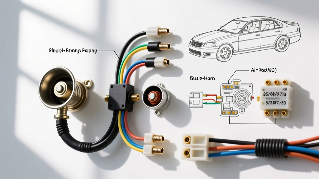
Introduction to Horn Circuit Upgrades and Selection
The factory horn on most modern vehicles is an afterthought—a weak, single-note snail horn designed to meet bare minimum federal safety standards while keeping manufacturing costs low. When upgrading to high-decibel aftermarket options, understanding the underlying car horn wiring diagram is critical. Pushing high-amperage loads through a factory steering column clock spring or undersized OEM wiring will result in melted connectors, voltage drops, and catastrophic electrical failures.
This guide serves as a comprehensive product comparison and selection resource for automotive horn upgrades. We will break down the electrical requirements of single electromagnetic, dual high-frequency, and compressor-driven air horns, providing the exact wiring schematics, relay pinouts, and American Wire Gauge (AWG) specifications required for a safe, reliable installation.
Decoding the Standard OEM Car Horn Wiring Diagram
Before selecting an aftermarket product, you must understand the baseline OEM circuit. In 95% of modern vehicles, the horn button on the steering wheel does not carry the actual power load for the horn. Instead, it acts as a low-amperage trigger switch.
- The Clock Spring (Rotary Coupler): Located behind the steering wheel, this ribbon cable assembly maintains electrical continuity while the wheel turns. It is typically rated for a maximum of 2 to 3 amps. Running a direct 12-amp dual-horn load through this component will instantly vaporize the copper traces.
- The Trigger Wire: Usually a 16 AWG or 18 AWG wire (often Black/White or Green/Red depending on the manufacturer) that routes from the clock spring to the horn relay coil.
- The ISO Mini Relay: The workhorse of the circuit. The factory relay switches high-amperage battery power to the horn actuator based on the low-amperage signal from the steering wheel.
Product Selection: Single vs. Dual vs. Air Horns
Selecting the right horn depends on your acoustic needs, available mounting space, and your vehicle's electrical system capacity. Below is a comparison chart to help you choose the correct product category before consulting your specific car horn wiring diagram.
| Horn Type | Example Products | Avg Current Draw | Recommended Wire Gauge | Relay Requirement | Best Application |
|---|---|---|---|---|---|
| OEM-Style Single Snail | Bosch / Hella OE Replacement | 4A - 6A | 16 AWG | Factory 10A/15A Relay | Direct plug-and-play daily drivers |
| Dual High-Frequency | Hella Supertones / Fiamm Freeway Blasters | 10A - 14A (Combined) | 12 AWG (Main), 14 AWG (Branch) | Aftermarket 30A ISO Relay | Motorcycles, compact cars, loud traffic environments |
| Compressor Air Horns | VIAIR / Train Horn Kits | 20A - 40A (Compressor) | 10 AWG or 8 AWG | Heavy-Duty 40A+ Relay | Off-road trucks, SUVs, highway towing rigs |
Wiring Diagram Variations by Horn Type
Once you have selected your product, the wiring topology must match the electrical draw. Below are the specific diagram configurations for the three primary horn categories.
1. Direct Replacement (Single Electromagnetic)
If you are simply replacing a dead OEM snail horn with an identical aftermarket unit (e.g., a Bosch 1320), the factory car horn wiring diagram remains unchanged. You will utilize the existing 1/4-inch female spade connector. Expert Tip: Always apply a dab of dielectric grease to the spade terminal and use a heat-shrink sleeve over the connection. Single-prong horns ground through their mounting bracket. Ensure the mounting surface is bare metal, free of rust and paint, and torque the bracket bolt to 10-15 Nm to prevent resonance cracking.
2. High-Output Dual Electromagnetic (Parallel Wiring)
Dual horns, such as the popular Hella Supertones, require a dedicated aftermarket wiring harness. Never wire dual horns in series, as this splits the voltage (6V each), resulting in a weak, off-pitch sound. They must be wired in parallel.
- Pin 86 (Coil 12V+): Splice into the OEM horn trigger wire using a T-tap or, preferably, a soldered and heat-shrunk pigtail.
- Pin 85 (Coil Ground): Secure to a clean chassis ground using a ring terminal.
- Pin 30 (Battery 12V+): Run a 12 AWG wire directly to the positive battery terminal, protected by an inline 20A ATO blade fuse located within 18 inches of the battery.
- Pin 87 (Normally Open Output): Run a 12 AWG wire from the relay to a weatherproof distribution block, then split into two 14 AWG wires feeding the positive terminals of both horns.
3. Compressor-Driven Air Horns
Air horn kits introduce a high-draw 12V DC compressor. The standard ISO mini relay used in OEM car horn wiring diagrams will melt under the continuous 30A+ load of an air compressor. You must upgrade to a heavy-duty Bosch-style 40A relay or a solid-state contactor. Furthermore, the compressor requires a dedicated air tank and a pressure switch. The pressure switch acts as the secondary trigger, ensuring the compressor only runs when the tank drops below 120 PSI, preventing continuous amperage draw that could drain your battery or overheat the alternator.
Component Selection: Relays, Fuses, and Wire Gauges
Adhering to SAE J1128 standards for automotive wire selection is non-negotiable. Using undersized wire creates resistance, which generates heat and causes severe voltage drop. According to Littelfuse automotive relay specifications, matching the fuse to the wire gauge (not just the load) is how you prevent electrical fires.
| Max Amperage Load | Minimum Wire Gauge (AWG) | Inline Fuse Rating | Recommended Connector Type |
|---|---|---|---|
| 10A | 16 AWG | 10A | Standard 1/4' Spade / Metri-Pack 150 |
| 20A | 12 AWG | 20A | Weatherpack 2-pin / Ring Terminal |
| 30A | 10 AWG | 30A | Weatherpack 2-pin / Heavy-Duty Ring |
| 40A+ | 8 AWG | 40A or 50A MIDI Fuse | High-Amp Lugs / Anderson Powerpole |
Step-by-Step Installation & Routing Best Practices
- Disconnect the Battery: Always isolate the negative terminal before splicing into the clock spring trigger wire to prevent accidental airbag deployment or shorting the steering column module.
- Locate the Trigger: Use a digital multimeter (DMM) to probe the OEM horn harness. The trigger wire will show 0V at rest, and 12V when the horn button is depressed. If your vehicle uses a negative-switching (ground trigger) system, you must use a relay inversion circuit or a specialized negative-trigger relay harness.
- Route the Power Feed: Run the main 12V power wire through the firewall or along the frame rail, utilizing split-loom tubing and zip ties. Keep the harness away from exhaust manifolds and moving suspension components.
- Weatherproofing: When mounting dual or air horns behind the grille, ensure the horn trumpets are angled slightly downward. This prevents water pooling, which causes internal diaphragm corrosion and frozen contacts. Use adhesive-lined marine-grade heat shrink on all terminal crimps.
Troubleshooting Common Horn Circuit Failures
Even with a perfect car horn wiring diagram, real-world variables can cause issues. Use this decision tree to diagnose post-installation faults.
| Symptom | Probable Cause | Diagnostic Fix |
|---|---|---|
| Horn sounds weak, low-pitched, or 'farts' | Severe voltage drop at the horn terminal or poor chassis ground. | Perform a voltage drop test with a DMM. Place leads on the battery positive and horn positive while sounding the horn. A reading over 0.5V indicates wire resistance or a failing relay. Clean the mounting ground. |
| Horn does not stop sounding when button is released | Relay contacts have welded shut due to excessive amperage draw or lack of a flyback diode. | Immediately pull the horn fuse. Replace the ISO relay with a heavy-duty 40A unit featuring an internal diode to suppress inductive voltage spikes. |
| Horn works intermittently or only when turning the steering wheel | Failing clock spring ribbon cable or loose steering column connector. | Bypass the steering column trigger temporarily by jumping the relay coil (Pins 85 and 86) directly to 12V. If the horn works perfectly, the fault lies upstream in the clock spring assembly. |
| Blown inline fuse immediately upon pressing the button | Dead short in the power feed wire or seized horn actuator. | Disconnect the horn(s) from the harness. If the fuse still blows, the power wire is pinched against the chassis. If the fuse holds, test the horn's internal coil resistance (should be 1 to 3 ohms). A reading of 0 ohms means a dead internal short. |
Final Thoughts on Horn Circuit Integrity
Upgrading your vehicle's auditory safety systems is one of the most cost-effective modifications you can perform. However, treating the electrical supply as an afterthought is a recipe for failure. By selecting the correct product for your application, strictly adhering to AWG sizing charts, and respecting the limits of the OEM clock spring via a properly configured relay harness, your upgraded horn system will deliver reliable, ear-splitting performance for the life of the vehicle. For further reading on standard automotive relay pinouts, consult the Hella TechWorld electrical archives.