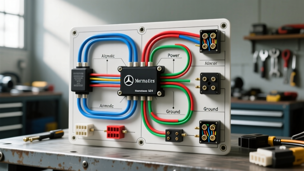
W212/W213 Airmatic Architecture Overview
The Mercedes-Benz E350, encompassing the W212 (2010-2016) and W213 (2017-2023) chassis generations, utilizes the Airmatic semi-active air suspension system. Unlike passive coilover setups, Airmatic relies on a complex network of CAN bus communication, high-amperage pneumatic generation, and precise Pulse Width Modulation (PWM) sensor feedback. Understanding the air suspension wiring diagram Mercedes E350 schematics requires moving beyond simple continuity testing and into the realm of network topology, voltage drop analysis, and oscilloscope signal validation.
At the heart of the system is the Airmatic Control Unit (designated as N51 in Mercedes-Benz Workshop Information System documentation). The N51 module orchestrates the air compressor (A9/1), the solenoid valve block (A9/1y1), and the four ride-height sensors (B22 series). According to Mercedes-Benz STAR TekInfo, the N51 module is integrated into the vehicle's CAN B (Interior/Comfort) network, requiring precise wake-up signals and termination resistance to function without throwing U-codes (communication faults).
N51 Control Module Pinout & Wire Color Specifications
The N51 control module is typically located in the right rear of the engine compartment or the trunk area depending on the exact model year and LHD/RHD configuration. Below is a critical reference table for the primary N51 connector pinout, highlighting OEM wire colors and AWG specifications. Note that Mercedes-Benz uses DIN standard color abbreviations (e.g., rd/gn for Red with Green tracer).
| Pin | Function / Designation | Wire Color (OEM) | AWG Size | Notes / Tolerance |
|---|---|---|---|---|
| 1 | Terminal 30 (12V+ Constant) | Red/Green (rd/gn) | 10 AWG | Fused via Front SAM (40A) |
| 2 | Terminal 31 (Chassis Ground) | Brown (br) | 10 AWG | Torque ground bolt to 10 Nm |
| 15 | CAN B High (H) | Orange/Green (og/gn) | 22 AWG | Twisted pair, 2.5V idle |
| 16 | CAN B Low (L) | Orange/Brown (og/br) | 22 AWG | Twisted pair, 2.5V idle |
| 24 | Level Sensor FL (PWM Return) | Yellow/Black (ye/bk) | 20 AWG | Shielded cable drain wire |
| 31 | Compressor Relay Trigger | Blue/White (bu/wh) | 18 AWG | Low-side driver to Front SAM |
Compressor Power Distribution & Front SAM Integration
The A9/1 air compressor is a high-draw inductive load, frequently pulling between 30A and 40A during initial pressurization phases. The wiring diagram routes this heavy current through the Front Signal Acquisition Module (SAM). The SAM houses a heavy-duty relay (often designated K51/1 or similar) and a 40A Maxi or Mega fuse.
Wire Gauge & Voltage Drop Diagnostics
The power feed from the Front SAM to the compressor pigtail is routed using 8 AWG or 10 AWG wiring. A common failure mode in the W212 E350 is a voltage drop across this circuit due to micro-corrosion at the SAM connector pins or the compressor spade terminals. When diagnosing a "Vehicle Rising Too Slowly" fault, do not merely check for 12V presence. You must perform a loaded voltage drop test. With the compressor actively running, measure the voltage drop across the positive feed wire and the ground return wire. A combined voltage drop exceeding 0.5V indicates excessive resistance, which starves the compressor motor, reduces its RPM, and triggers thermal protection shutdowns prematurely.
Level Sensor (B22) PWM Signal Topography
The ride-height sensors (B22/15 Left Front, B22/16 Right Front, etc.) are not simple potentiometers. They are Hall-effect sensors that output a Pulse Width Modulation (PWM) square wave signal. The N51 module provides a 5V reference and a sensor ground. The return signal wire carries a square wave where the duty cycle correlates directly to the suspension's physical ride height.
- Normal Ride Height: ~50% Duty Cycle (approx. 2.5V average DC)
- Maximum Extension (Lift Mode): ~80-90% Duty Cycle
- Maximum Compression (Lowered): ~10-20% Duty Cycle
Oscilloscope Setup for Sensor Validation
To properly diagnose a level sensor circuit using an oscilloscope, configure your scope with DC coupling, a 5V/div scale, and a 10ms timebase. Probe the PWM return wire at the N51 connector using a back-probe to maintain weatherpack integrity. If the waveform shows jagged edges, ringing, or drops to 0V intermittently, inspect the sensor harness where it routes near the strut tower. This area is highly susceptible to debris impact and chafing against the inner fender liner. For deeper network analysis, referencing SAE International standards on PWM and vehicle networks provides excellent baseline parameters for signal integrity and noise rejection.
Valve Block Solenoids & Flyback Diode Protection
The A9/1y1 valve block contains multiple solenoids responsible for routing air to individual struts and the exhaust valve. Each solenoid coil typically measures between 12 and 18 ohms at room temperature. Because these are highly inductive loads, the N51 control module utilizes internal flyback diodes to suppress the voltage spike (inductive kickback) generated when the solenoid is deactivated.
Critical Warning: Never apply a generic 12V test light or an unregulated power probe directly to the solenoid control wires at the N51 connector. Doing so can back-feed voltage into the module's sensitive driver transistors, instantly destroying the internal flyback circuitry and requiring a complete N51 replacement. Always test solenoid resistance statically with a digital multimeter (DMM) at the valve block connector.
Advanced Troubleshooting Decision Matrix
Use the following matrix to isolate complex electrical faults within the Mercedes E350 Airmatic system:
Symptom: Compressor Runs Continuously Until Thermal Cutoff
- Electrical Cause: Welded contacts inside the Front SAM compressor relay. The N51 module is no longer commanding the relay, but the physical contacts are fused together, supplying constant Terminal 30 power to the compressor.
- Pneumatic Cause: Severe leak in the valve block or air strut, causing the N51 module to genuinely command a 100% duty cycle to maintain pressure.
- Diagnostic Fix: Disconnect the N51 trigger wire at the SAM relay. If the compressor continues to run, the relay is welded and the SAM must be serviced/replaced. If the compressor stops, perform an overnight pneumatic leak-down test using soapy water or UV dye on the strut air bladders.
Symptom: "Airmatic Visit Workshop" with CAN U-Codes
- Electrical Cause: Loss of CAN B termination resistance or water ingress in the N51 X4 connector.
- Diagnostic Fix: Measure the resistance between CAN H (Pin 15) and CAN L (Pin 16) at the N51 connector with the battery disconnected. You should read approximately 60 ohms (indicating two 120-ohm terminating resistors in parallel on the network). If you read 120 ohms, you have an open circuit in the CAN bus daisy chain. If you read near 0 ohms, there is a short between the Orange/Green and Orange/Brown wires.
Grounding & Shielding Best Practices
When repairing any Airmatic wiring harness, maintaining OEM shielding standards is non-negotiable. The PWM sensor wires are routed as shielded twisted pairs to prevent electromagnetic interference (EMI) from the high-amperage compressor wiring and the engine ignition system. When splicing a damaged sensor wire, you must solder the connection, seal it with marine-grade heat shrink, and properly re-attach the bare copper shield drain wire to the module ground. Furthermore, all M6 and M8 chassis ground bolts for the Airmatic system must be cleaned to bare metal and torqued precisely to 10 Nm to 15 Nm to ensure the N51 module's analog-to-digital converters have a clean 0V reference plane.