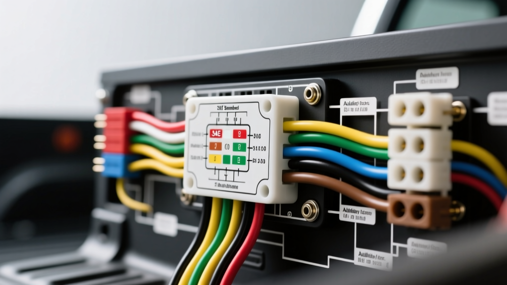
Introduction to CM Truck Bed Electrical Architecture
Installing or troubleshooting a CM Truck Bed (such as the CM SK flatbed, CM ER service body, or CM BRT) requires a thorough understanding of both the OEM chassis wiring and the aftermarket upfitter harness. Unlike standard pickup truck beds, CM service bodies utilize a complex network of lighting circuits, auxiliary 12V power feeds for toolboxes, and high-draw LED work lights. The central nervous system of this setup is the IP67-rated junction box typically mounted beneath the bed crossmembers, which interfaces directly with the truck’s factory 7-way RV blade connector and upfitter switch bank.
This technical specification reference provides the exact CM truck bed wiring diagram parameters, SAE-compliant wire color codes, AWG sizing requirements, and chassis integration protocols for Ford, Ram, and GM heavy-duty platforms. Whether you are integrating a new CM bed onto a chassis cab or diagnosing a parasitic draw in an existing setup, adhering to these electrical schematics is critical for DOT compliance and preventing Body Control Module (BCM) faults.
Standard 7-Way RV Blade Pinout & SAE Color Codes
The primary interface between the truck chassis and the CM bed harness is the 7-way RV blade connector. While CM Truck Beds utilizes heavy-duty, sealed looms, the pinout adheres strictly to the SAE J286 and RVIA (Recreation Vehicle Industry Association) standards. Below is the definitive pinout matrix for the CM bed main pigtail.
| Pin | Function | Standard Wire Color | AWG Size | CM Bed Specific Notes |
|---|---|---|---|---|
| 1 | Left Turn / Stop | Yellow | 14 AWG | Feeds left tail pan and side markers. |
| 2 | Reverse Lights | Black (or Orange) | 14 AWG | Ties into CM backup strobes and toolbox floods. |
| 3 | Ground (White) | White | 10 AWG | Must be ring-terminated to bare chassis frame. |
| 4 | Right Turn / Stop | Green | 14 AWG | Feeds right tail pan and side markers. |
| 5 | Electric Brakes | Blue | 12 AWG | Pass-through for trailer towing; capped in bed harness. |
| 6 | 12V Auxiliary Power | Red | 10 AWG | Powers bed relays, beacon lights, and air compressors. |
| 7 | Tail / Running Lights | Brown | 14 AWG | Feeds all perimeter DOT clearance and marker lights. |
The Grounding Imperative (Pin 3)
The most common failure point in any CM truck bed wiring diagram is the ground circuit. The 7-way connector provides a 10 AWG white ground wire, but this is often insufficient for fully loaded service bodies running high-amp LED floodlights and toolbox compressors. Best Practice: Install a dedicated 8 AWG ground wire directly from the CM bed’s main IP67 junction box to a clean, bare-metal point on the chassis frame. Use a star washer to bite through the paint and coat the terminal with dielectric grease to prevent galvanic corrosion.
Chassis Upfitter Integration: Ford & Ram Aux Switches
Modern heavy-duty trucks feature dedicated upfitter switches designed specifically for aftermarket beds like those from CM. Properly integrating these switches ensures that auxiliary bed lights, crane hydraulics, and toolbox compressors do not overload the factory wiring.
Ford Super Duty (F-250/F-350/F-450) Upfitter Integration
Ford provides a blunt-cut pigtail under the hood (near the driver’s side battery) and a pass-through grommet in the firewall.
- Switch 1 (S1): Orange/Light Green (30A)
- Switch 2 (S2): White/Blue (30A)
- Switch 3 (S3): White/Red (30A)
- Switch 4 (S4): White/Brown (30A)
Ram Heavy Duty (2500/3500) Aux Switch Bank
Ram utilizes an electronic Aux Switch panel (typically S1-S4 at 30A, S5-S8 at 40A). Unlike Ford’s physical relays, Ram’s aux outputs are solid-state and controlled via the Uconnect interface. When wiring a CM bed accessory to a Ram aux switch, ensure the load does not exceed 25A continuous. If wiring a CM toolbox air compressor, use the Ram aux output to trigger a heavy-duty 100A continuous-duty solenoid mounted directly in the bed toolbox, drawing primary current directly from the auxiliary battery.
Auxiliary Power, Toolbox Wiring, and Deutsch Connectors
CM Truck Beds frequently equips service bodies with modular LED work lights, strobe modules, and toolbox power feeds. For these auxiliary circuits, standard blade connectors are unacceptable due to vibration and moisture exposure. CM utilizes Deutsch DT series connectors for all exterior auxiliary lighting.
- Deutsch DT 2-Pin: Used for individual LED scene lights. Requires 14 AWG wire, solid copper crimp pins, and the orange secondary lock wedge.
- Deutsch DT 4-Pin: Used for multi-function strobe modules and heated mirrors.
- Superseal 1.5: Often found on the IP67 junction box sensor inputs (e.g., tailgate open sensors for interior bed lighting).
When repairing or extending these harnesses, always use adhesive-lined, dual-wall heat shrink tubing (3:1 shrink ratio) to ensure a watertight seal. Standard electrical tape will degrade under UV exposure and chassis heat, leading to copper oxidation and voltage drop.
Wire Routing & Loom Protection Standards
According to SAE J1128 standards for low-tension primary cable, wires routed beneath the CM bed must be protected from road debris, exhaust heat, and moving suspension components.
- Split Loom Tubing: Use nylon split loom for harnesses routed inside enclosed toolbox cavities.
- Convoluted Tubing (Closed Slit): Mandatory for any harness running along the exterior frame rails. Secure with UV-resistant zip ties every 12 inches.
- Thermal Shielding: Any wiring passing within 6 inches of the exhaust DPF/SCR system must be wrapped in fiberglass or basalt sleeve insulation rated to 1000°F.
Diagnostic Troubleshooting Matrix
When diagnosing electrical faults in a CM service body, the issue is rarely a broken wire; it is almost always a connector, ground, or BCM logic fault. Use the following matrix to isolate the problem.
| Symptom | Probable Root Cause | Diagnostic Step & Fix |
|---|---|---|
| LED Tail Lights Hyperflash | BCM detects low current draw (LEDs draw less amperage than incandescent bulbs). | Install SAE J2801 compliant CANbus load resistors (typically 6 ohm, 50W) in parallel with the turn signal circuit at the IP67 box. |
| Toolbox Compressor Runs Slow / Overheats | Severe voltage drop on the 12V Aux (Red) wire due to undersized wire or long run. | Measure voltage at the compressor under load. If below 11.5V, upgrade the feed from 10 AWG to 8 AWG and verify chassis ground. |
| Running Lights Flicker at Idle | Alternator AC ripple leaking into the DC circuit due to a poor bed ground. | Test AC voltage on the brown wire with the engine running. If >0.5V AC, clean the main frame ground and install a 12V DC filter capacitor. |
| Ford Uconnect/Ram Dash Shows 'Trailer Wiring Fault' | Moisture ingress in the 7-way plug causing cross-talk between Pin 7 (Brown) and Pin 3 (White). | Inspect the 7-way receptacle. Spray with CRC QD Electronic Cleaner and apply dielectric grease. Replace if pins are green with corrosion. |
Authoritative References & Standards
For further engineering specifications regarding aftermarket truck bed wiring and heavy-duty chassis integration, consult the following resources:
- SAE International J286: Standard for 7-way connectors and trailer/bed lighting circuits.
- CM Truck Beds Official Resources: Upfitter manuals, warranty guides, and body-specific schematics.
- eTrailer Wiring FAQ & Standards: Practical application guides for RV and flatbed 7-way pinouts and load resistor integration.
Always disconnect the negative battery terminals on both the chassis and auxiliary batteries before cutting, splicing, or modifying any CM truck bed wiring harness to prevent short circuits and BCM damage.