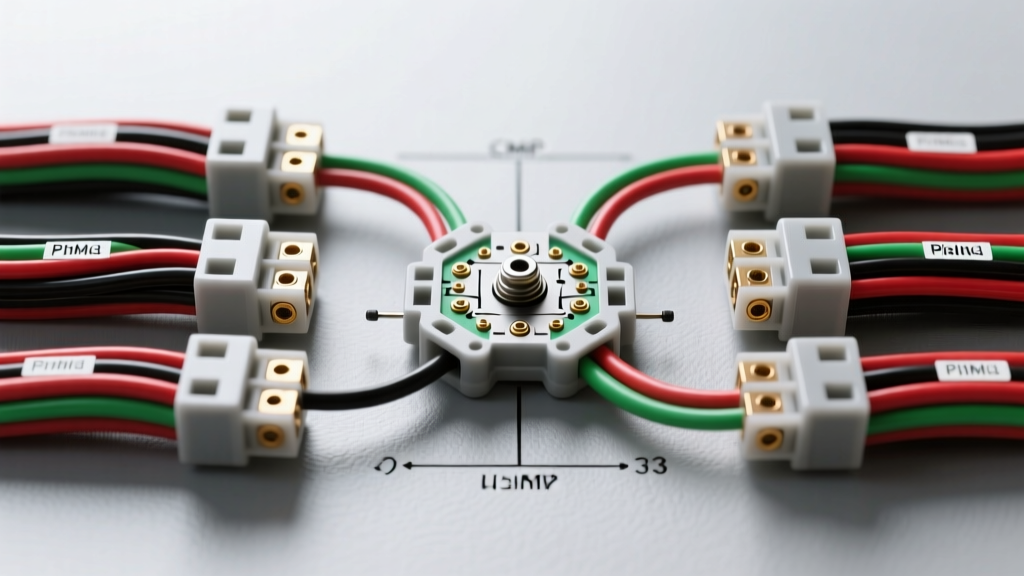
Understanding the Camshaft Position Sensor (CMP)
The Camshaft Position Sensor (CMP) is a critical engine management component that tells the Powertrain Control Module (PCM) the exact rotational position of the camshaft. Without this data, the PCM cannot synchronize sequential fuel injection or optimize ignition timing. When a CMP fails or its wiring degrades, your engine may experience a no-start condition, severe misfires, or default to a degraded "limp-home" mode using only the Crankshaft Position Sensor (CKP).
For beginners stepping into automotive electrical diagnostics, the camshaft sensor wiring diagram is your roadmap. It translates a complex web of copper into a logical circuit you can test with a basic Digital Multimeter (DMM). This guide breaks down the fundamentals of CMP wiring, focusing on the most common modern configuration: the 3-wire Hall Effect sensor.
How to Read a Camshaft Sensor Wiring Diagram
Factory Service Manuals (FSM) and aftermarket databases use standardized symbols to represent electrical circuits. When you open a camshaft sensor wiring diagram, you will typically see three main elements:
- The PCM/ECM Block: Represented as a large rectangle with numbered pins. The diagram will specify the exact cavity number (e.g., Pin 42 for Signal Return).
- The Sensor Connector: Shown as a female or male terminal interface, often with a dotted line indicating the physical connector housing.
- Splices and Grounds: Indicated by a solid black dot (splice) or a standard chassis ground symbol (a line with three descending horizontal hash marks).
Beginners often make the mistake of assuming wire colors in the diagram perfectly match the vehicle in their driveway. While OEM diagrams list the primary color and tracer (e.g., Dark Green/White), aftermarket diagrams might simplify this. Always verify your specific vehicle's wire colors using a dedicated repair database, as mid-year production changes can alter harness colors.
The 3-Wire Hall Effect Sensor Standard
Most modern vehicles (from the late 1990s to present) utilize a 3-wire Hall Effect camshaft sensor. Unlike older 2-wire Variable Reluctance (VR) sensors that generate their own alternating current (AC) voltage based on magnetic reluctance, Hall Effect sensors require an external power source to operate. They output a clean, digital square-wave Direct Current (DC) signal that the PCM can read at very low engine cranking speeds.
A standard 3-wire camshaft sensor wiring diagram will always feature these three circuits:
- Reference Voltage (Power): Usually 5 volts (sometimes 8V or 12V depending on the OEM), supplied by the PCM.
- Sensor Ground: A dedicated low-resistance return path to the PCM, not a generic chassis ground.
- Signal Return: The digital square-wave output that toggles between 0 volts and the reference voltage as the camshaft reluctor wheel passes the sensor.
Typical CMP Pinout and Wire Specification Chart
While exact pinouts vary by manufacturer (GM, Ford, Toyota, etc.), the fundamental electrical characteristics of a 3-wire Hall Effect CMP remain consistent. The table below outlines the standard specifications you will encounter when diagnosing these circuits.
| Pin / Circuit | Function | Typical OEM Wire Color | Wire Gauge (AWG) | Expected Voltage / State |
|---|---|---|---|---|
| Pin 1 (Power) | 5V Reference Supply | Red, Pink, or Orange | 18 AWG - 20 AWG | 4.8V - 5.2V (Key On, Engine Off) |
| Pin 2 (Ground) | PCM Sensor Ground | Black, Black/White | 18 AWG - 20 AWG | Less than 0.1V (Voltage Drop Test) |
| Pin 3 (Signal) | Digital Signal Return | Yellow, Green, or Gray | 18 AWG - 20 AWG | Toggles 0V to 5V (Engine Cranking) |
Note: Automotive sensor circuits typically use 18 AWG or 20 AWG cross-linked polyethylene (XLPE) wire. This gauge is thick enough to prevent voltage drop over the length of the engine harness, yet flexible enough to withstand constant engine vibration and thermal expansion.
Step-by-Step Multimeter Testing for Beginners
You do not need an expensive oscilloscope to perform fundamental diagnostics on a camshaft sensor circuit. A quality Digital Multimeter (DMM) with a high-impedance input (minimum 10 Megohms) is sufficient. According to diagnostic procedures outlined by Haynes Manuals, follow these steps to verify circuit integrity without damaging the wiring.
Step 1: The Back-Probing Technique
Never pierce the wire insulation with a T-pin or needle to test a sensor circuit. Piercing the jacket exposes the copper to moisture, leading to capillary corrosion that will eventually destroy the harness from the inside out. Instead, use dedicated back-probe pins or a small, straightened paperclip to gently slide into the back of the connected sensor plug (the wire side) to make contact with the metal terminal.
Step 2: Verify the 5V Reference
Set your DMM to DC Volts. Connect the black lead to the battery negative terminal and the red lead to your back-probe on the Power pin. Turn the ignition to the "ON" position (engine off). You should read between 4.8V and 5.2V. If you read 0V, you have an open circuit or a PCM internal fault. If you read 12V, you may be testing a specific OEM system that uses battery voltage for the Hall sensor (common in some older Chrysler applications).
Step 3: Verify the Sensor Ground
Leave the ignition ON. Move your red DMM lead to the battery positive terminal, and move your black DMM lead to the Ground pin back-probe. You are performing a voltage drop test. A healthy PCM ground circuit should read less than 0.1V. If you read 4V or higher, the ground wire is broken, or the PCM ground terminal is corroded.
Step 4: Check the Signal Output
Connect your black DMM lead to the battery negative and the red lead to the Signal pin. Have an assistant crank the engine. Because a DMM cannot refresh fast enough to display a rapid square wave, it will display an "average" DC voltage. For a 5V reference system, a healthy toggling signal will typically average out to roughly 2.5V to 3.0V while cranking. If the voltage stays pinned at 5V or drops to 0V and does not fluctuate, the sensor is dead, the reluctor wheel is missing teeth, or the signal wire is shorted.
Common Wiring Faults and Connector Issues
When consulting a comprehensive CMP diagnostic guide, you will find that the sensor itself is often not the root cause of a P0340 (Camshaft Position Sensor Circuit Malfunction) code. The wiring harness and connectors endure extreme abuse. Here are the most common real-world failure modes:
1. Terminal Fretting and Micro-Corrosion
Engine vibration causes the male and female terminals inside the sensor connector to rub against each other microscopically. This wears away the tin or gold plating, leading to oxidation (fretting). This adds resistance to the 5V reference circuit, causing the sensor to brown out and drop the signal. Fix: Clean terminals with electrical contact cleaner and apply a light coat of dielectric grease to seal out moisture.
2. Oil Capillary Action (Wicking)
If the internal O-ring seal on the camshaft sensor fails, engine oil can pressurize into the sensor connector. Over time, oil will wick (travel via capillary action) up inside the wire insulation, eventually reaching the PCM connector. This is a catastrophic failure mode that can ruin the engine control module. Fix: If you find oil inside the CMP connector, you must replace the sensor, clean the harness with aerosol brake cleaner, and potentially replace the entire pigtail.
3. Heat Shield Degradation
Camshaft sensors are often mounted near exhaust manifolds or cylinder heads. OEMs route the harness with braided fiberglass or aluminum heat shields. If a previous mechanic removed this shielding during a timing belt or valve cover service, the ambient 250°F+ radiant heat will melt the XLPE wire insulation, leading to a short-to-ground on the signal circuit. Always reinstall heat shielding and use high-temp zip ties.
Advanced Note: Variable Valve Timing (VVT) Interference
On modern engines equipped with VVT, the PCM uses the CMP signal to monitor the actual position of the camshaft relative to the commanded position. If your wiring tests perfectly, but you still have a correlation code (e.g., P0011 or P0014), do not blame the wiring. These codes usually indicate a mechanical failure, such as a clogged VVT oil control solenoid screen, stretched timing chain, or a failed phaser lock-pin. The wiring diagram only proves the electrical integrity; it cannot diagnose oil pressure or mechanical timing faults.
Summary
Mastering the camshaft sensor wiring diagram is a foundational skill for any DIY mechanic or aspiring technician. By understanding the 3-wire Hall Effect topology, respecting the delicate nature of 18 AWG sensor wires, and utilizing proper back-probing techniques, you can accurately diagnose CMP faults without causing secondary damage to the vehicle's electrical system. Always reference OEM-specific pinouts and wire colors before applying voltage to any circuit.